Switch magnetic resistance motor power converter short-circuit fault bus current diagnosis method

A technology for switched reluctance motors and power converters, which is applied in short-circuit testing, motor control, and measurement of electrical variables, etc., and can solve the problems that fault diagnosis methods cannot be directly applied to switched reluctance motor power converters, etc., and achieve the short circuit of the main switch The effect of accurate fault diagnosis, extensive engineering application value, and simple method

Active Publication Date: 2014-03-26
CHINA UNIV OF MINING & TECH
View PDF5 Cites 25 Cited by
  • Summary
  • Abstract
  • Description
  • Claims
  • Application Information

AI Technical Summary

Problems solved by technology

[0002] The switched reluctance motor system has a power supply mode of non-sinusoidal current and non-sinusoidal voltage, and operates on the principle of minimum reluctance, but the fault diagnosis method of the traditional motor power converter cannot be directly applied to the switched reluctance motor power converter
At present, most of the fault diagnosis methods for switched reluctance motor power converters are aimed at the short-circuit fault of the main switch of double-switch power converters.

Method used


Image

  • Switch magnetic resistance motor power converter short-circuit fault bus current diagnosis method
  • Switch magnetic resistance motor power converter short-circuit fault bus current diagnosis method
  • Switch magnetic resistance motor power converter short-circuit fault bus current diagnosis method

Examples


Embodiment 1

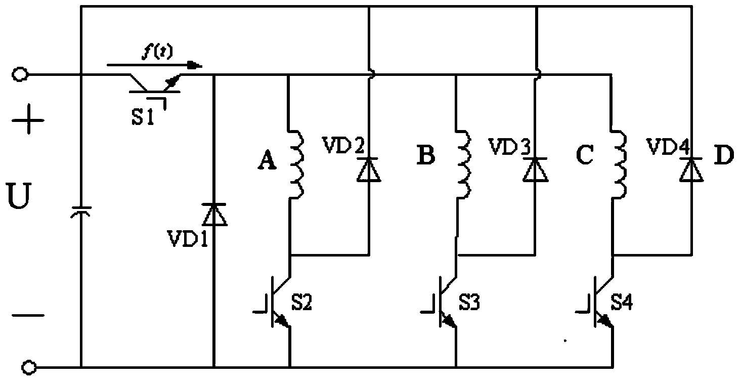
[0019] Embodiment one: if figure 1 Shown is the main circuit of the three-phase public switched reluctance motor power converter, each phase of the three-phase public switched reluctance motor power converter has a main switch and a freewheeling diode, A phase, B phase Phase C and phase C are connected in parallel to the negative pole "-" of the power supply U, and phase A, phase B and phase C are connected in parallel to the positive pole "+" of the power supply U through the common switch S1 and the public freewheeling diode VD1. One end of the public switch S1 is connected to the positive pole "+" of the power supply, the other end of the public switch S1 is connected to one end of the A-phase winding, the position of the A-phase main switch S2 is connected to the negative pole "-" of the power supply, and the main switch of the A-phase position is The other end of S2 is connected to the other end of the A-phase winding, one end of the A-phase freewheeling diode VD2 is conn...

Embodiment 2

[0028] Embodiment two: if Figure 5 As shown, it is the main circuit of the three-phase double-switch switched reluctance motor power converter. Each phase of the three-phase double-switch has two main switches and two freewheeling diodes. Phase A, phase B and phase C are connected in parallel for power supply The positive pole "+" and the negative pole "-" of the power supply U are on; one end of the upper main switch S1 of phase A is connected to the positive pole "+" of the power supply U, the other end of the upper main switch S1 is connected to one end of the A phase winding, and one end of the lower main switch S2 It is connected to the negative pole "-" of the power supply U, the other end of the lower main switch S2 is connected to the other end of the A phase winding, one end of the upper freewheeling diode VD1 is connected to the positive pole "+" of the power supply U, and the other end of the upper freewheeling diode VD1 is connected to the A phase winding. The oth...


PUM


Abstract

Provided is a switch magnetic resistance motor power converter short-circuit fault bus current diagnosis method. A bus current instantaneous value of a switch magnetic resistance motor power converter is detected so that a mean value delta of maximum values of a wavelet transformation coefficient corresponding to bus current under different scale parameters is calculated and acts as fault characteristic quantity. A main switch short-circuit fault on the position of the switch magnetic resistance motor power converter is diagnosed by using a mean value delta curve of the maximum values of the wavelet transformation coefficient corresponding to the bus current of the switch magnetic resistance motor power converter under different scale parameters within the whole speed range. The diagnosis method is applicable to diagnosis of the main switch short-circuit fault on the position of the switch magnetic resistance motor power converter with various topological structures and various phases, accurate in short-circuit fault diagnosis and great in engineering application value.

Description

technical field [0001] The invention relates to a method for diagnosing the bus current of a short-circuit fault of a main switch at a position of a power converter of a switched reluctance motor, especially a short-circuit fault of the main switch at the position of a power converter of a switched reluctance motor suitable for various phase numbers and various topological structures. Diagnostic methods for bus currents. Background technique [0002] The switched reluctance motor system has a power supply mode of non-sinusoidal current and non-sinusoidal voltage, and operates on the principle of minimum reluctance, but the fault diagnosis method of the traditional motor power converter cannot be directly applied to the switched reluctance motor power converter. At present, most of the fault diagnosis methods for switched reluctance motor power converters are aimed at the short-circuit fault of the main switch of double-switch power converters. The public switching power con...

Claims


Application Information

Patent Timeline
Patent Type & Authority Applications(China)
IPC IPC(8): G01R31/02
CPCG01R31/343G01R31/42H02P25/092H02P29/0241G01R31/52G01R31/50H02P29/024
Inventor 陈昊王星王胜权
Owner CHINA UNIV OF MINING & TECH
Why Eureka
Try Eureka