Infrared circuit box failure diagnosis device

A fault diagnosis and infrared circuit technology, applied in the direction of electronic circuit testing, etc., can solve the problems of insufficient product testing and high requirements for maintenance personnel, and achieve the effect of increasing the automatic testing process and ensuring accuracy

Inactive Publication Date: 2014-03-26
中国人民解放军济南军区72465部队
View PDF0 Cites 0 Cited by
  • Summary
  • Abstract
  • Description
  • Claims
  • Application Information

AI Technical Summary

Problems solved by technology

[0003] At present, the maintenance of the infrared circuit box mainly depends on the inspection and maintenance equipment. On the one hand, the inspection of the product is not comprehensive enough;

Method used


Image

  • Infrared circuit box failure diagnosis device

Examples


Embodiment Construction

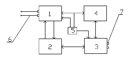
[0016] The infrared circuit box fault diagnosis equipment includes a main control system, an excitation signal generation part, a data acquisition part and a panel.

[0017] The main control system includes a PC104 main board 3, which realizes data exchange with PC104 bus, fault analysis, etc. As the main control part of the system, the PC104 motherboard is embedded in the operating system and touch screen system, which is very convenient to realize human-computer interaction.

[0018] The excitation signal generation part includes a signal conditioning board 1, a detection cable 6 and a power supply 5, and the signal conditioning board includes at least an attenuation filter circuit, a precision voltage source circuit, a power-on control circuit, and a power conversion. The precision voltage source circuit adopts MAX6341, and the input +15V voltage passes through MAX6341 to form a reference voltage of 4.096V, which is used as a reference voltage for A / D sampling, and C1 / C4 i...


PUM


Abstract

The invention relates to an infrared circuit box failure diagnosis device. The infrared circuit box failure diagnosis device adopts the following technical scheme that the infrared circuit box failure diagnosis device comprises a master control system, an excitation signal generation portion, a data acquisition portion and a panel. The master control system comprises a PC104 mainboard. The excitation signal generation portion comprises a signal conditioning board, a detection cable and a power source. The signal conditioning board at least comprises an attenuation filter circuit, a precise voltage source circuit, a power-on control circuit, and a source transformation circuit. The data acquisition portion comprises a data acquisition board based on a PC104 bus. The excitation signal generation portion is used to provide a power source and various required excitation signals for detected products. The master control system is responsible for the control and data processing of the whole system. According to the invention, not only the detect that detection parameters of an infrared circuit box detection maintenance equipment are not comprehensive is overcome to ensure the detection accuracy, validity and automaticity, and but also a specialist diagnosis system is implant onto the software, so failures can be judged and positioned accurately, and the maintenance operation can be effectively guided, so that infrared circuit box failure diagnosis device is suitable for being popularized and used in all levels of service stations.

Description

technical field [0001] The invention belongs to the field of weapon detection equipment, and in particular relates to a weapon infrared circuit box fault diagnosis equipment. Background technique [0002] In the maintenance process, two conditions are required: the first is the detection condition, that is, to provide power and excitation conditions for the product, and then use a multimeter or oscilloscope to detect various parameters of the product; the second is the expert condition, and the expert uses its solid Professional knowledge and rich experience analyze these parameters to find the cause of the failure. [0003] At present, the maintenance of the infrared circuit box mainly depends on the inspection and maintenance equipment. On the one hand, the inspection of the product is not comprehensive enough. Contents of the invention [0004] The invention proposes an infrared circuit box fault diagnosis device which integrates detection conditions and expert conditi...

Claims


Application Information

Patent Timeline
Patent Type & Authority Applications(China)
IPC IPC(8): G01R31/28
Inventor 王新段武杨金春罗先锋丁国营陈鹤方传磊袁清峰
Owner 中国人民解放军济南军区72465部队
Why Eureka
Try Eureka