Composite pulse generation circuit

A technology for generating circuits and composite pulses, applied in the field of power electronics, can solve problems such as limited application range and unreasonable structure, and achieve the effect of simple circuit topology and control mode, simple structure, and good film effect

Active Publication Date: 2014-03-26
西安国创电子股份有限公司
View PDF6 Cites 2 Cited by
  • Summary
  • Abstract
  • Description
  • Claims
  • Application Information

AI Technical Summary

Problems solved by technology

[0014] The purpose of the present invention is to provide a compound pulse generating circuit, which solves the problems of unreasonable structure and limited application range in the prior art

Method used


Image

  • Composite pulse generation circuit
  • Composite pulse generation circuit
  • Composite pulse generation circuit

Examples


Embodiment Construction

[0046] The present invention will be further described below in conjunction with the drawings and specific embodiments.

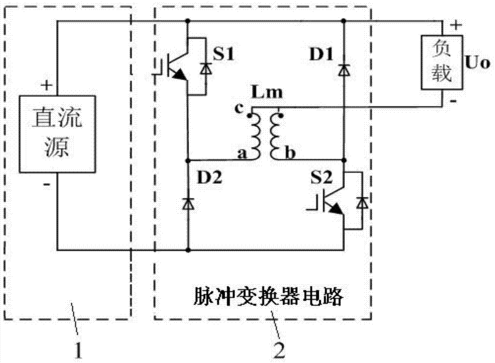
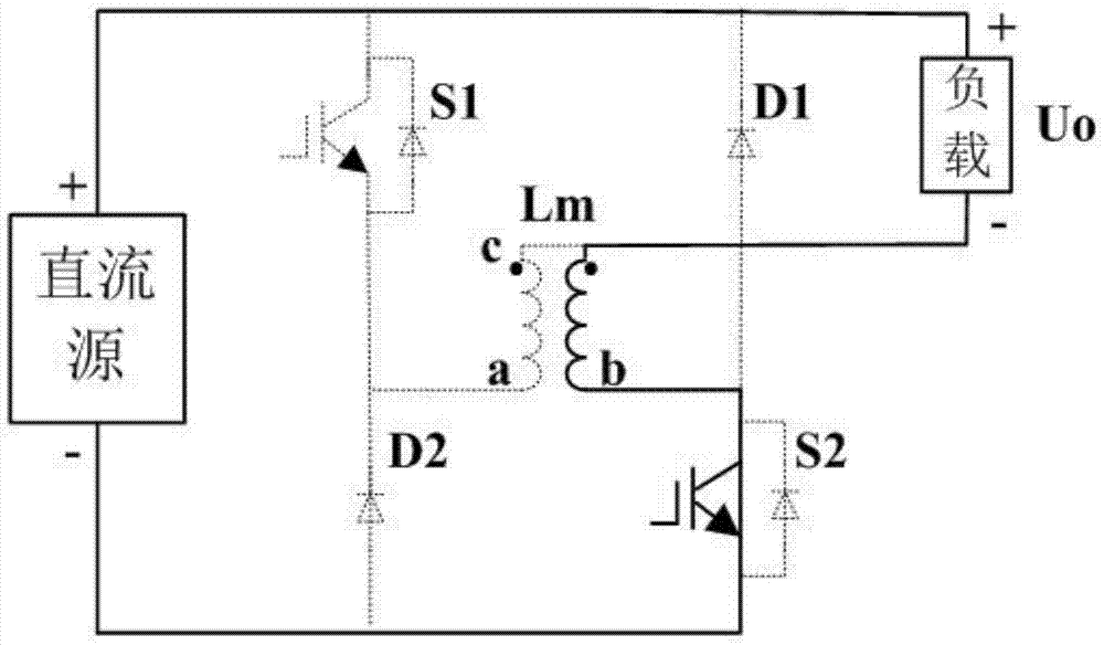
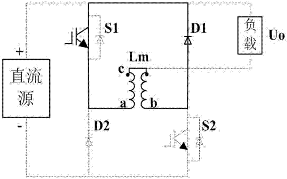
[0047] Such as figure 1 , The circuit topology of the composite pulse generating circuit of the present invention includes a DC source 1 and a pulse converter circuit 2. The pulse converter circuit 2 includes a switch tube S 1 , S 2 , Diode D 1 , D 2 , And coupled inductance Lm, the specific circuit topology is:

[0048] Positive pole of DC source 1 and switch tube S 1 The collector and diode D 1 Connect the cathode of the DC source 1 to the diode D 2 The anode and switch tube S 2 Emitter connection; switch tube S 1 The emitter is connected to the diode D 2 The cathode of the coupled inductor Lm is connected at the same time, the diode D 1 The anode of the switch tube S 2 The collector of the coupled inductor Lm is connected at the same time, the switch tube S 1 The collector and diode D 1 The cathode is connected to the positive wire of the load, and the c termin...


PUM


Abstract

The invention discloses a composite pulse generation circuit, comprising a direct current source, wherein the anode of the direct current source is connected with the collector of a switching tube S1 and the cathode of a diode D1, the cathode of the direct current source is connected with the anode of a diode D2 and the emitter of a switching tube S2, the emitter of the switching tube S1 is respectively connected with the cathode of the diode D2 and the a end of a coupling inductor Lm at the same time, the anode of the diode D1 is respectively connected with the collector of the switching tube S2 and the b end of the coupling inductor Lm at the same time, the collector of the switching tube S1 and the cathode of the diode D1 are connected with the positive lead wire of a load, and the c end of the coupling inductor Lm is connected wit the negative lead wire of the load. According to the composite pulse generation circuit provided by the invention, multiple kinds of waveform output, such as bidirectional multi-level asymmetrical pulse, bipolar asymmetrical pulse, unipolar pulse and direct current, are achieved by controlling the on-off of the switching tubes S1 and S2.

Description

Technical field [0001] The invention belongs to the technical field of power electronics and relates to a composite pulse generating circuit. Background technique [0002] Due to the on-off characteristics of the pulse, a high-intensity alternating pulse electric field can be generated between the electrodes, which can achieve phenomena or effects that are difficult to achieve under DC electric field conditions. Therefore, it is widely used in surface treatment, metal processing, sewage treatment and Military, aerospace and other fields. [0003] Pulse power supply often has special requirements on the shape of pulse waveform under different conditions of use. The load environment and purpose are different, the required pulse mode and voltage level are different, and different pulse types and amplitudes are even required at different times in the working state diagram. . The shape of the pulse waveform often has a greater impact on the processing effect of the corresponding appli...

Claims


Application Information

Patent Timeline
Patent Type & Authority Applications(China)
IPC IPC(8): H02M9/02
Inventor 陈桂涛孙强钟彦儒
Owner 西安国创电子股份有限公司
Why Eureka
Try Eureka