

Radio frequency feed-forward amplifier and loop self-adaptive control method
A technology of power amplifier and feedback power, applied in the field of mobile communication
- Summary
- Abstract
- Description
- Claims
- Application Information
AI Technical Summary
Problems solved by technology
Method used
Image

Examples
Embodiment 1
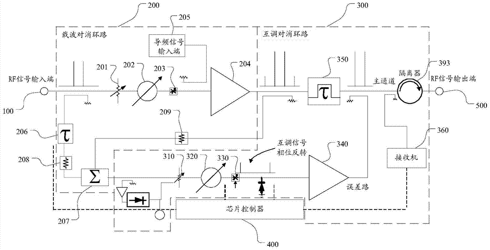
[0024] Such as figure 1 As shown, a radio frequency feedforward power amplifier includes a carrier cancellation loop 200, an intermodulation cancellation loop 300, and a chip controller 400. The amplitude modulator 201, the phase modulator 202, the first gain equalizer 203, the main power amplifier 204, the other input end of the main power amplifier 204 is coupled to the pilot signal input end 205, and the delay line coupled to the radio frequency signal input end 100 206, and a combiner 207 coupled to the delay line 206 and the output of the main power amplifier 204; the intermodulation cancellation loop 300 includes a phase adjustment circuit 310, a gain adjustment circuit 320, a second gain equalizer 330, an error Power amplifier 340, delay filter 350, receiver 360, described combiner 207 is connected with gain adjustment circuit 320, second gain equalizer 330, error power amplifier 340 input end successively through phase adjustment circuit 310, and described delay filter...
Embodiment 2
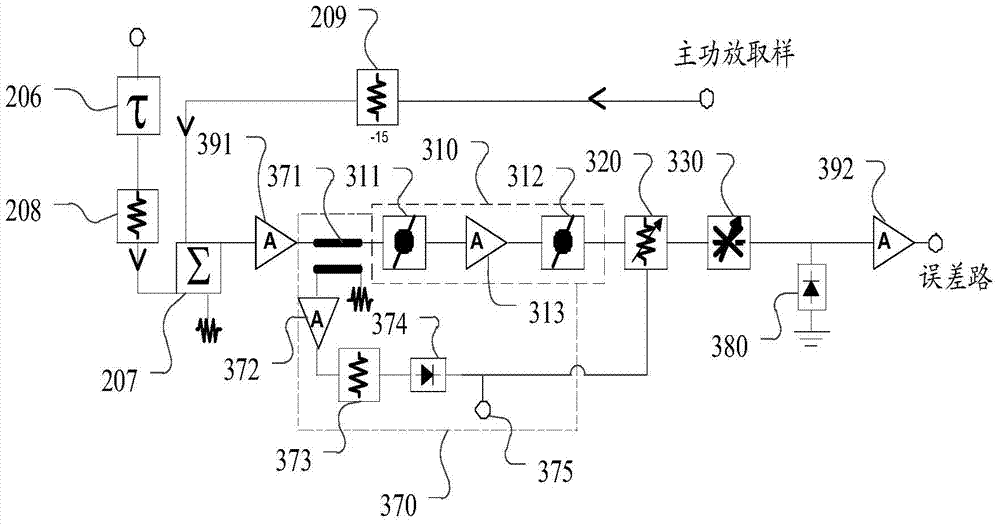
[0028] The main difference between the second embodiment and the first embodiment is that the radio frequency feedforward power amplifier also includes a loop real-time protection circuit.
[0029] Such as figure 1 , figure 2 As shown, a radio frequency feedforward power amplifier includes a carrier cancellation loop 200, an intermodulation cancellation loop 300, a chip controller 400, and a loop real-time protection circuit 370 located at the intermodulation cancellation loop 300 :
[0030] The carrier cancellation loop 200 includes an amplitude modulator 201, a phase modulator 202, a first gain equalizer 203, a main power amplifier 204 connected to the radio frequency signal input terminal 100 in turn, and the other input terminal of the main power amplifier 204 is connected with the pilot signal The input terminal 205 is coupled and connected, the delay line 206 coupled with the radio frequency signal input terminal 100, and the combiner 207 coupled with the delay line 2...
PUM
 Abstract
Description
Claims
Application Information