
Heat dissipation optimizing structure for precise device in inertial navigation product

A technology of inertial navigation and structure optimization, applied in cooling/ventilation/heating transformation, etc., can solve the problems of the performance, life and reliability of precision devices, the temperature rise of the surface of precision devices and the environment, and the performance of each functional module of the product. , to achieve rapid equilibrium of thermal field, improvement of working environment temperature, and good heat dissipation effect.

Active Publication Date: 2014-03-26
SHAANXI BAOCHENG AVIATION INSTR
View PDF12 Cites 1 Cited by
  • Summary
  • Abstract
  • Description
  • Claims
  • Application Information

AI Technical Summary

Problems solved by technology

[0002] For inertial navigation electronic products, the system integration level continues to increase, the system power consumption continues to increase, and the box volume continues to decrease, resulting in an increase in the temperature rise of the surface of precision devices and the environment, which directly affects the performance of each functional module of the product, resulting in Degradation of precision device performance, lifetime and reliability
In addition, temperature has a great influence on the accuracy of precision devices. When the temperature rises, the parameter drift will increase, resulting in a decrease in the performance and life of precision devices, which will eventually affect the performance and life of the product. Therefore, heat dissipation for precision devices is a must. A very important link in product thermal design

Method used


Image

  • Heat dissipation optimizing structure for precise device in inertial navigation product
  • Heat dissipation optimizing structure for precise device in inertial navigation product
  • Heat dissipation optimizing structure for precise device in inertial navigation product

Examples


Embodiment Construction

[0018] Attached below Figure 1-4 An embodiment of the present invention is described.

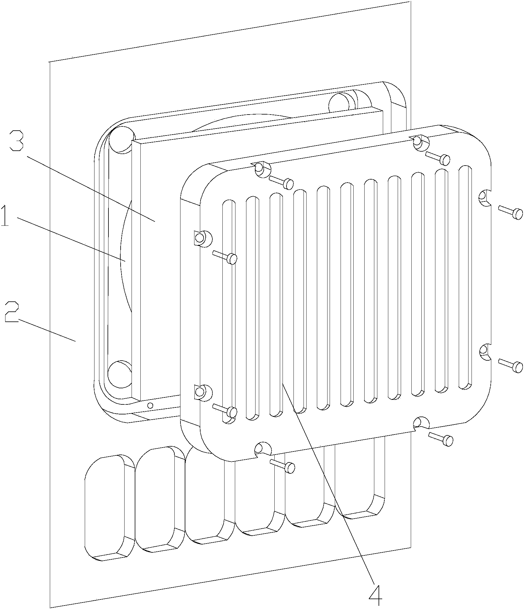
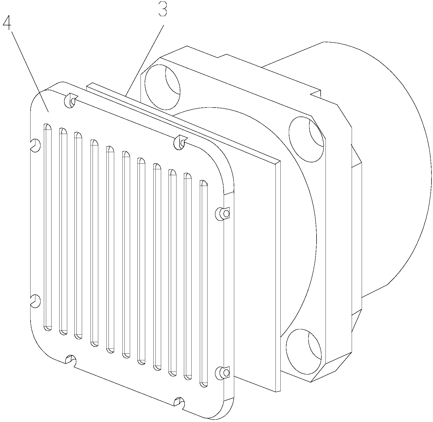
[0019] It is used for the heat dissipation optimization structure of precision devices in inertial navigation products. The precision device 1 is put into the installation hole of the box body 2 and the gap between the two is filled with a soft silicone heat conduction sheet 3. One side of the soft silicone heat conduction sheet 3 and the precision The surface of the device 1 is in close contact, and the other side of the soft silicone heat-conducting sheet 3 is in close contact with the rear surface of the heat sink 4 fixedly connected to the box body 2 . Specifically, the heat dissipation device 4 is a fin radiator, and the fin radiator is fixedly connected with the box body 2 as a whole through mounting screws, and the fin radiator is made of aluminum.

[0020] As we all know, the structure design of inertial navigation electronic products is a fully sealed structure. The internal heat...


PUM


Abstract

The invention provides a heat dissipation optimizing structure for a precise device in an inertial navigation product. The precise device is contained in an installation hole of a box body and a gap between the precise device and the box body is filled with a soft silica gel heat-conductive fin. One face of the soft silica gel heat-conductive fin makes tight contact with the surface of the precise device and the other face of the soft silica gel heat-conductive fin makes tight contact with the rear surface of a heat dissipation device fixedly connected with the box body. The soft silica gel heat-conductive fin is arranged in the gap between the precise device and the box body so that the air gap can be eliminated, thermal contact resistance between the precise device and the box body can be reduced, heat generated by the precise device can be rapidly conducted to the surface of the box body, a thermal field inside the product can be balanced rapidly, and influence on performance indexes of the precise device by the environment temperature can be reduced. Meanwhile, heat is dissipated in a conductive mode, a convective mode and a radiant mode, so that the heat dissipation effect is good, the reliability of the product is improved, the service life of the product is prolonged, the structure is easy to obtain, and the usability is high.

Description

technical field [0001] The invention belongs to the technical field of thermal design of inertial navigation products, and in particular relates to a heat dissipation optimization structure for precision devices in inertial navigation products. Background technique [0002] For inertial navigation electronic products, the system integration level continues to increase, the system power consumption continues to increase, and the box volume continues to decrease, resulting in increased temperature rise on the surface of precision devices and the environment, directly affecting the performance of each functional module of the product, resulting in Degradation of precision device performance, lifetime and reliability. In addition, temperature has a great influence on the accuracy of precision devices. When the temperature rises, the parameter drift will increase, resulting in a decrease in the performance and life of precision devices, which will eventually affect the performanc...

Claims


Application Information

Patent Timeline
Patent Type & Authority Applications(China)
IPC IPC(8): H05K7/20
Inventor 王鹏范超穆菲菲寇学锋黄凯杨宏智江军肖兵
Owner SHAANXI BAOCHENG AVIATION INSTR
Learn More