Complicated-shape double-layer pipe manufacturing method and sealing device
A technology of complex shapes and manufacturing methods, applied in the field of complex shape double-layer tube manufacturing methods and sealing devices, can solve the problems of inability to manufacture complex shapes, large volume of double-layer tubes, high manufacturing costs, etc., and achieve high engineering application value and preparation process Simple, long-lasting effect
- Summary
- Abstract
- Description
- Claims
- Application Information
AI Technical Summary
Problems solved by technology
Method used
Image
Examples
Embodiment 1
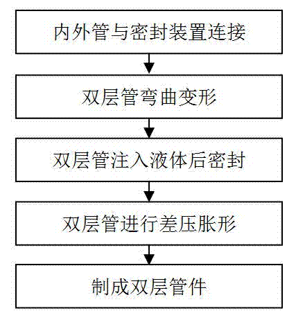
[0031] The first step is to select a carbon steel pipe blank with a pipe diameter of 40 mm and a length of 500 mm as the inner pipe 2, such as figure 2 As shown, weld both ends of the inner tube 2 to the sealing device 1, and use 8 M5 bolts to strengthen the combination of the inner tube 2 and the sealing device 1;
[0032] The second step is to put the sealing device 1 and the inner pipe 2 into another carbon steel billet outer pipe 3 with a pipe diameter of 50 mm and a length of 540 mm, such as image 3 As shown, the two ends of the outer tube 3 are welded to the sealing device 1, and then 16 M5 bolts are used to strengthen the combination of the outer tube 3 and the sealing device 1, as shown in Figure 6 shown;
[0033] The third step is to use a bending die on the press to bend and deform the fully assembled double-layer pipe until the shape of the outer pipe 3 becomes V-shaped, such as Figure 7 shown;
[0034] The fourth step is to use the hydraulic cylinder to simu...
Embodiment 2
[0039] The first step is to select a stainless steel tube blank with a diameter of 30 mm and a length of 600 mm as the inner tube 2, such as figure 2 As shown, after the surface of the inner tube 2 is cleaned, the two ends and the sealing device 1 are welded together by surfacing welding, and eight M5 bolts are used to strengthen the combination of the inner tube 2 and the sealing device 1;
[0040] The second step is to put the sealing device 1 and the inner tube 2 into another stainless steel tube blank outer tube 3 with a diameter of 40 mm and a length of 640 mm, such as image 3 As shown, the two ends of the outer tube 3 are welded to the sealing device 1, and then 16 M5 bolts are used to strengthen the combination of the outer tube 3 and the sealing device 1, as shown in Figure 6 shown;
[0041] The third step is to bend the fully assembled double-layer pipe on the push bending machine, control the bending speed to avoid pipe rupture, and change the shape of the outer ...
Embodiment 3
[0047] The first step is to use the 316 stainless steel tube blank with excellent corrosion resistance as the inner tube 2, with a diameter of 40 mm and a length of 700 mm, such as figure 2 As shown; first clean the surface of the inner tube, and then weld the two ends of the inner tube 2 to the sealing device, and use 8 M5 bolts to strengthen the combination of the inner tube 2 and the sealing device 1;
[0048] In the second step, the outer pipe 3 selects a low-cost carbon steel billet with a pipe diameter of 50 mm and a length of 740 mm. Put the sealing device 1 and the inner tube 2 into the outer tube 3, such as image 3 As shown, the two ends of the outer tube 3 are welded to the sealing device 1, and then 16 M5 bolts are used to strengthen the combination of the outer tube 3 and the sealing device 1, as shown in Figure 6 shown;
[0049] The third step is to use a three-roller roll bender to perform roll bending deformation on the fully assembled double-layer tube, an...
PUM
| Property | Measurement | Unit |
|---|---|---|
| Diameter | aaaaa | aaaaa |
| Length | aaaaa | aaaaa |
| Diameter | aaaaa | aaaaa |
Abstract
Description
Claims
Application Information
 - R&D
- Intellectual Property
- Life Sciences
- Materials
- Tech Scout
- Unparalleled Data Quality
- Higher Quality Content
- 60% Fewer Hallucinations
Browse by: Latest US Patents, China's latest patents, Technical Efficacy Thesaurus, Application Domain, Technology Topic, Popular Technical Reports.
© 2025 PatSnap. All rights reserved.Legal|Privacy policy|Modern Slavery Act Transparency Statement|Sitemap|About US| Contact US: help@patsnap.com


