Single-row multilayer winding machine for strip product

A multi-layer, winder technology, which is applied in the direction of winding strips, thin material handling, transportation and packaging, etc. Copper bar conductivity and other issues, to achieve the effect of low cost, improved winding efficiency and good winding effect

Active Publication Date: 2014-04-02
XIAN METALWK HYDRAUMATIC MACHINERY
View PDF10 Cites 10 Cited by
  • Summary
  • Abstract
  • Description
  • Claims
  • Application Information

AI Technical Summary

Problems solved by technology

Among them, straight strips can only be used for shorter products, generally 3m to 6m long, which can facilitate vehicle transportation, but when straight strips are used on site, if a 100m-long transmission line needs to be erected, it needs Connect multiple 6m long straight strips with joints, which greatly affects the conductivity of the copper bar
And this bundled straight strip discharge has the following disadvantages in the use process: 1. The bundled discharge products are inconvenient to transport and require large lifting equipment; 2. When constructing in the field, large transportation tools are required; 3. Bundles of nesting products occupy a large area in the warehouse
If the length of the product is longer, it is necessary to use multi-layer and multi-row coil materials. The following disadvantages exist in the use of multi-layer and multi-row coil materials: 1. Multi-layer and multi-row coil products need to be straightened and bent before use; 2. 1. The weight of multi-layer and multi-row plate products is heavy, and large-scale lifting equipment is required for transportation; 3. During field construction, multiple people are required to cooperate in transportation, which is labor-intensive; 4. Multi-person cooperative transportation is very prone to safety accidents

Method used


Image

  • Single-row multilayer winding machine for strip product
  • Single-row multilayer winding machine for strip product
  • Single-row multilayer winding machine for strip product

Examples


Embodiment Construction

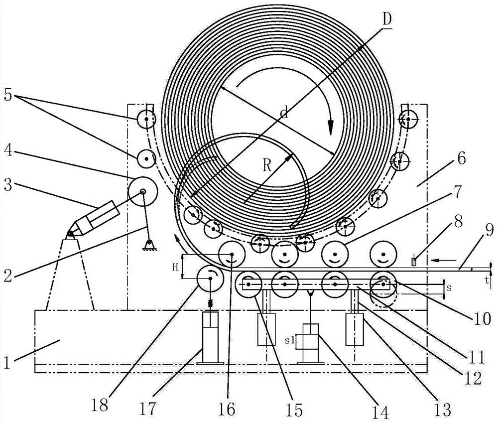
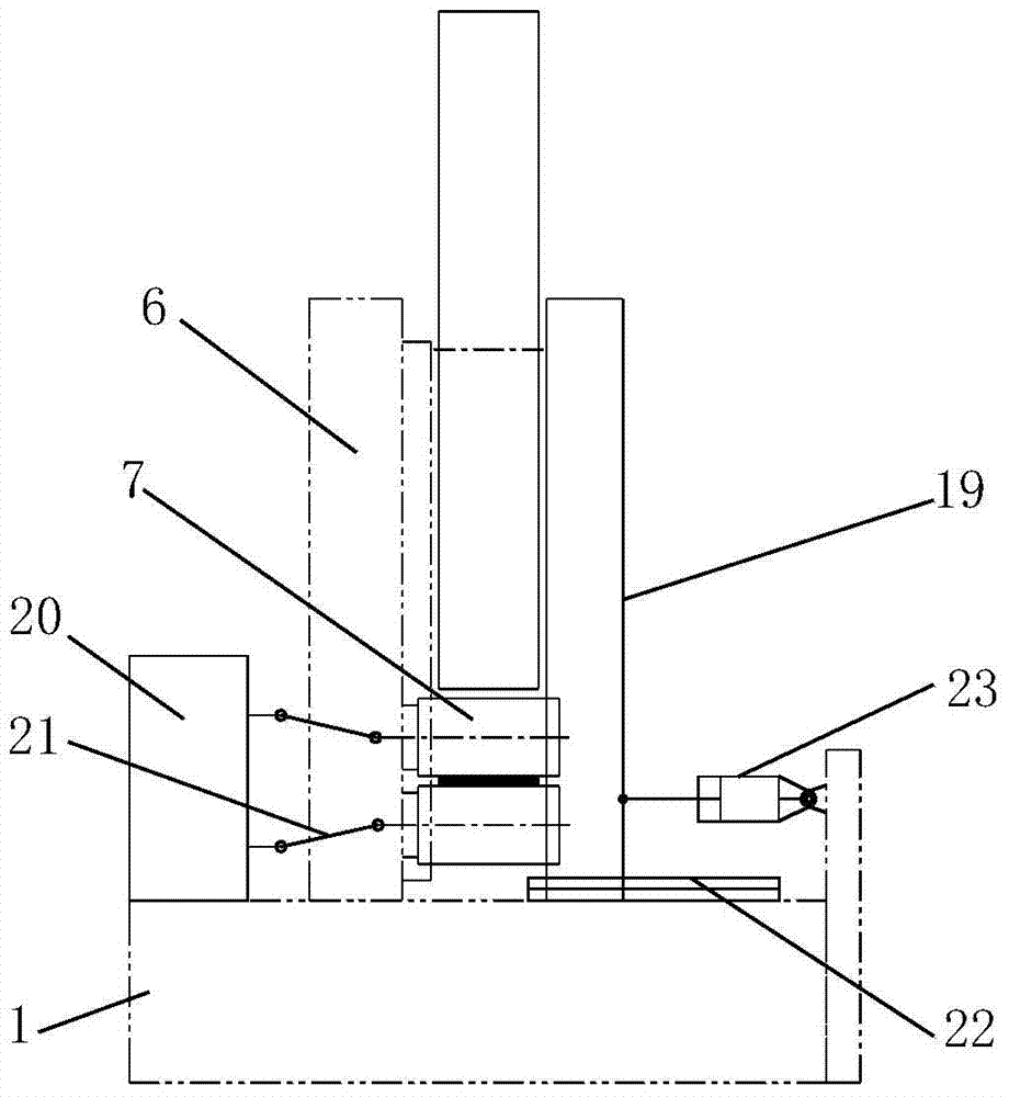
[0042] Such as figure 1 with figure 2 The single-row multi-layer winding machine for strip products shown includes a frame 1 and a first baffle plate 6 arranged on the frame 1. The first baffle plate 6 is on and along the product 9 A lower pinch roller 10, a bending support roller 15 and a bending roller 18 are arranged in the running direction in sequence. The upper pinch roller 10 is provided with an upper pinch that cooperates with the lower pinch roller 10 and is used to pinch products 9 The first baffle plate 6 is provided with a curved fixed roller 16 that cooperates with the curved support roller 15 and the curved roller 18 and makes the product 9 bend upwards. The curved fixed roller 16 is located on the curved support roller 15 and the curved Above the connecting line between the rollers 18, the frame 1 is provided with a power mechanism 20 for driving the upper pinch roller 7, the lower pinch roller 10, the bending support roller 15, the bending fixed roller 16 and th...


PUM


Abstract

The invention discloses a single-row multilayer winding machine for a strip product. The single-row multilayer winding machine for the strip product comprises a rack and a first striker plate arranged on the rack. Bottom pinch rolls, a bending supporting roll and a bending roll are arranged on the first striker plate in sequence along the moving direction of the product; top pinch rolls matched with the bottom pinch rolls and used for pinching the product are respectively arranged above the bottom pinch rolls; the first striker plate is provided with a bending fixed roll matched with the bending supporting roll and the bending roll and used for bending the product upwards; the rack is provided with a power mechanism used for driving the top pinch rolls, the bottom pinch rolls, the bending supporting roll, the bending fixed roll and the bending roll to rotate; the first striker plate is hinged to a plurality of supporting rolls used for supporting the whole roll of product; the supporting rolls are arranged at intervals along the bending radian of the bottom part of the whole roll of product. According to the single-row multilayer winding machine for the strip product, the product can be effectively wound, and therefore the transportation and the packaging of the product are facilitated, the storage space of the product is saved, and the use of the product at the construction site is also facilitated.

Description

Technical field [0001] The invention relates to a winding machine, in particular to a single-row multi-layer winding machine for strip products. Background technique [0002] At present, in the production process of copper row production line in many copper processing enterprises, the type of cut-to-length finished copper row is coil material or straight strip material, and the coil material is multi-layer and multi-row type. Among them, straight strips can only be applied to shorter products, generally 3m-6m long, which can facilitate vehicle transportation, but when straight strips are used on site, if a 100m-long transmission line needs to be erected, it is necessary Connect multiple 6m-long straight strips with joints, which greatly affects the conductivity of the copper bar. Moreover, this kind of bundled straight discharge has the following disadvantages in the use process: 1. The transportation of bundled discharge products is inconvenient and requires large lifting equip...

Claims


Application Information

Patent Timeline
Patent Type & Authority Applications(China)
IPC IPC(8): B65H18/08B65H20/02
Inventor 陈世雄王振中吉晓辉刘海艳武丹陈宁
Owner XIAN METALWK HYDRAUMATIC MACHINERY
Why Eureka
Try Eureka