Overground operating string delivery mechanism
A technology for conveying devices and operating strings, which is applied in the direction of drilling pipes, casings, and drilling equipment. It can solve problems such as large inertial force, time-consuming and labor-intensive efficiency, and unsafe human body, and achieve reduced contact, good compatibility, and enhanced safety. sexual effect
- Summary
- Abstract
- Description
- Claims
- Application Information
AI Technical Summary
Problems solved by technology
Method used
Image

Examples
Embodiment 1
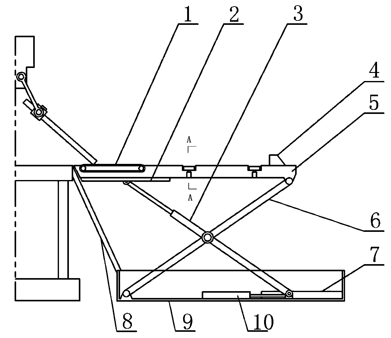
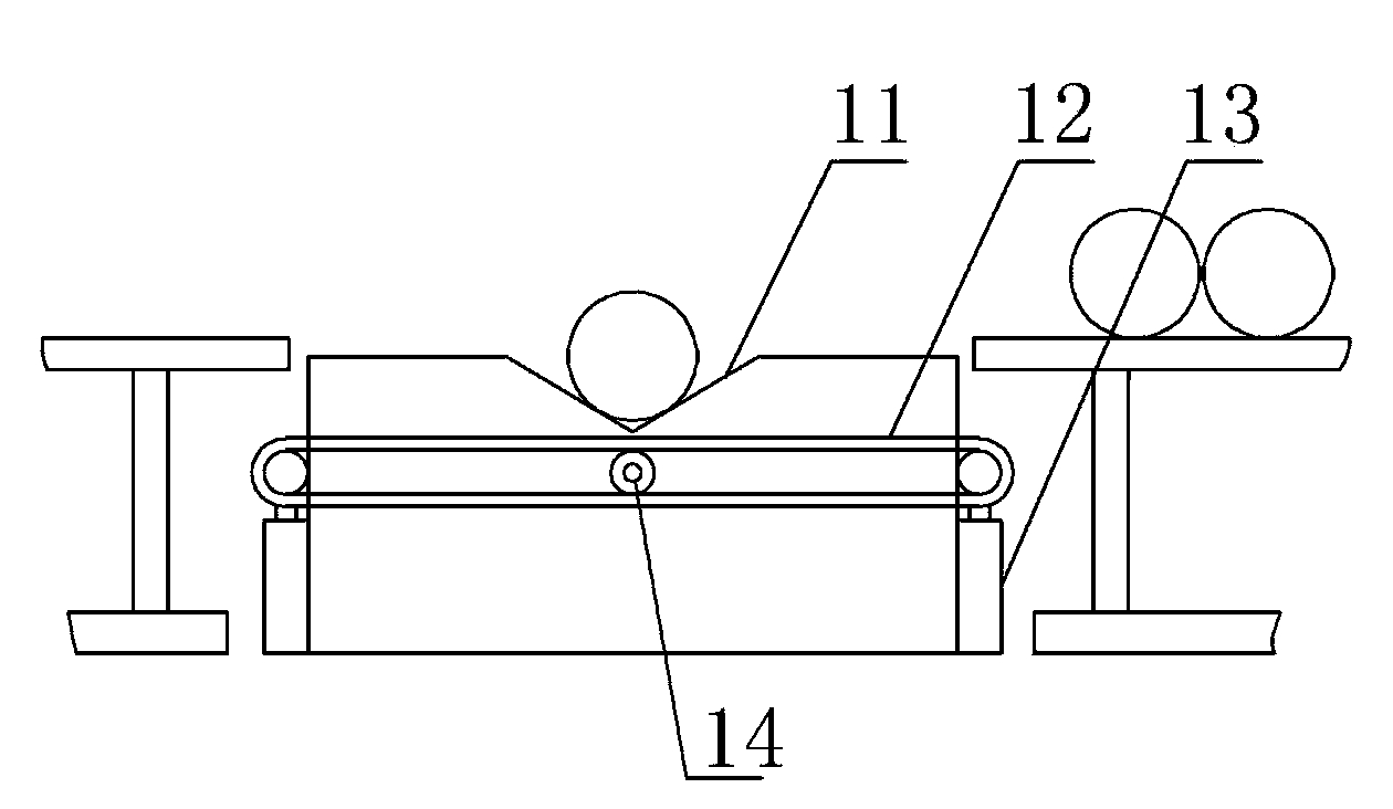
[0016] Embodiment 1: with reference to attached figure 1 , image 3 and Figure 4 , the lower end of the ramp 8 of the uphole operation pipe string delivery device of the present invention is connected to the catwalk support 9, the catwalk body 5 is above the catwalk support 9, and the upper end surface of the catwalk body 5 is horizontally provided with a V-shaped slideway 11. Drill block car 4 can slide in V-shaped slideway 11. A lifting support leg 6 and a sliding support leg 3 are connected between the catwalk body 5 and the catwalk support 9 . The two ends of the lifting support leg 6 are respectively hinged with the catwalk support 9 and the catwalk body 5, and the lifting support leg 6 and the sliding support leg 3 are hinged in an X shape at their respective midpoints. One end of the sliding support leg 3 slides in the lower track 7 , and the other end of the sliding support leg 3 slides in the upper track 2 and is connected to the horizontal hydraulic cylinder 10 ....
Embodiment 2
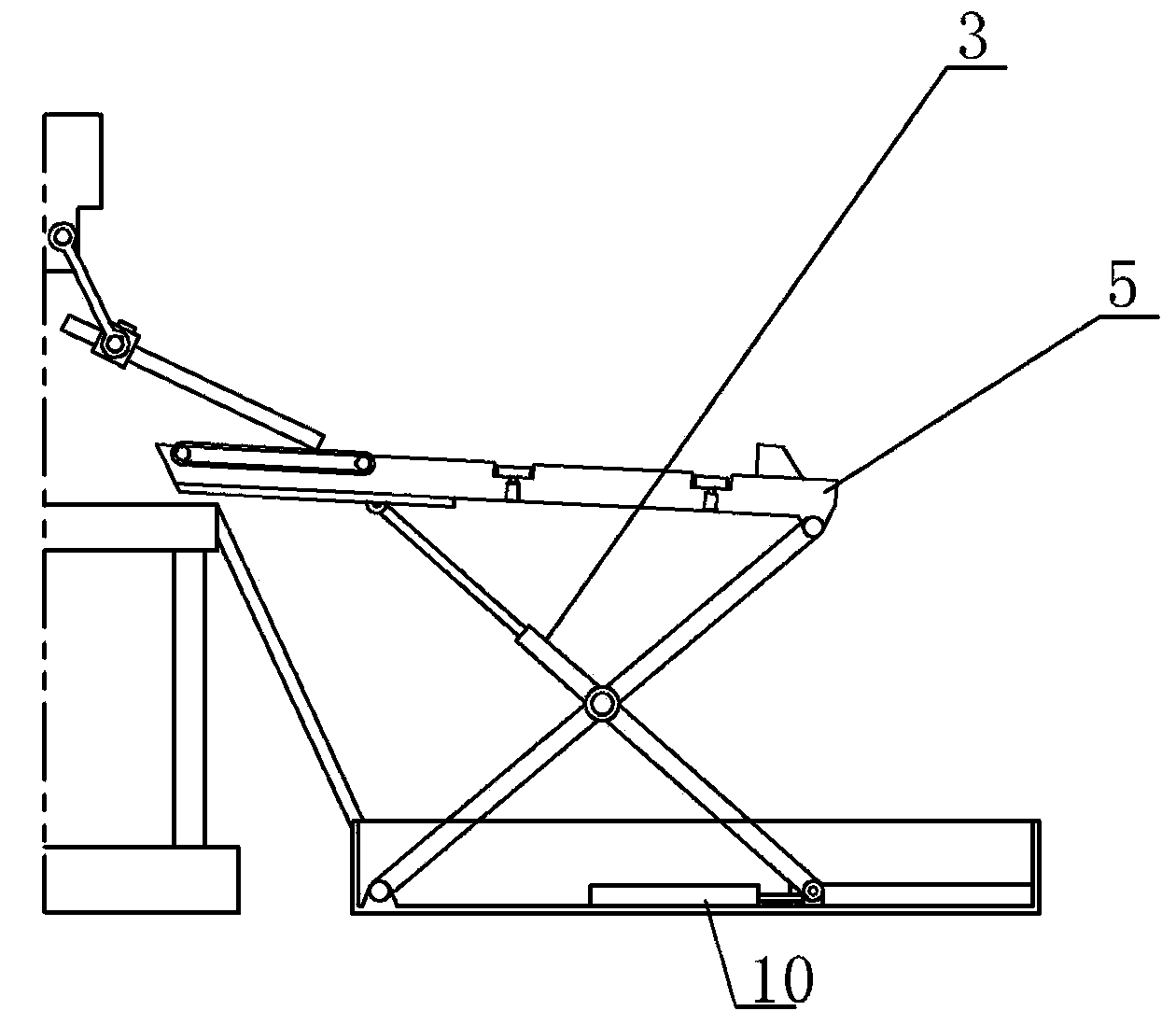
[0020] Embodiment 2: refer to figure 2 , on the basis of the structure of the uphole operation pipe string delivery device in Embodiment 1, the end of the sliding support leg 3 close to the catwalk body 5 is a telescopic arm with a built-in hydraulic cylinder.
[0021] The process of sending up the pipe string: first, the catwalk body 5 is in the initial position, the pipe row conveyor belt 12 moves the pipe string on the pipe rack to the V-shaped slideway 11, and the drilling block 4 moves to the pipe string along the V-shaped slideway And against one end of the pipe string. Then the telescopic arm extension of the sliding support leg 3 makes the end of the catwalk body 5 near the drill floor perk, and the catwalk body 5 is in an inclined state. The horizontal hydraulic cylinder 10 works, and the catwalk body 5 starts to lift. When the end of the catwalk body 5 close to the drill floor rises above the drill floor and approaches the wellhead, the lifting stops. At this time,...
PUM
 Abstract
Description
Claims
Application Information
 - Generate Ideas
- Intellectual Property
- Life Sciences
- Materials
- Tech Scout
- Unparalleled Data Quality
- Higher Quality Content
- 60% Fewer Hallucinations
Browse by: Latest US Patents, China's latest patents, Technical Efficacy Thesaurus, Application Domain, Technology Topic, Popular Technical Reports.
© 2025 PatSnap. All rights reserved.Legal|Privacy policy|Modern Slavery Act Transparency Statement|Sitemap|About US| Contact US: help@patsnap.com