Centering and leveling work platform for high-precision cylindricity measuring instrument

A workbench and cylindricity technology, applied in the field of measurement and detection, can solve the problems affecting cylindricity measurement accuracy, low feed accuracy, complex structure, etc., and achieve the effects of improving adjustment resolution, centering accuracy, and adjustment accuracy.

Active Publication Date: 2014-04-02
BEIJING AEROSPACE INST FOR METROLOGY & MEASUREMENT TECH +1
5 Cites 15 Cited by

AI-Extracted Technical Summary

Problems solved by technology

[0005] The existing manual centering and leveling workbench has a complex structure, heavy weight, and low feed accuracy. The resi...

Method used

The present invention adopts bevel gear steering box 5, self-aligning worm gear box 7 and self-aligning feed head 22 to carry out self-aligning, and utilizes bevel gear to convert the input and output angle of worm gear box, utilizes spring to add certain The pre-tightening force transmits the centering displacement through the rolling of the steel balls in the self-aligning ball plate, and replaces the sliding friction with rolling friction, which reduces the resistance and reduces the error to a certain extent, thereby improving the centering accuracy. The present invention adopts leveling worm gear box 9 and leveling feed head 24 to convert horizontal feed into vertical upward displacement feed, thereby realizing leveling. The feature of this structure is the use of a high-precision worm gear box with a large reduction ratio and a locking function, which replaces the conventional simple screw adjustment feed method and improves the adjustment resolution.
The steel ball 17 material at the bottom of the middle mounting plate is stainless steel, and there ...

Abstract

The invention belongs to the fields of measurement and detection, particularly relates to a centering and leveling work platform for a high-precision cylindricity measuring instrument and aims to provide the centering and leveling work platform which has the advantages of simpler structure, small regulating resistance and high feeding precision. The centering and leveling work platform comprises a centering device, a leveling device and a support device, wherein the centering device and the leveling device are mounted on the support device, the centering of the work platform is implemented by the centering device, and the leveling of the work platform is implemented by the leveling device. Centering is carried out through the adoption of a bevel gear steering box 5, a centering worm gear box 7 and a centering feeding head 22, and the input-output angle of the worm gear box is converted by a bevel gear. Besides, a spring is utilized to apply a certain pre-tightening force, centering shift is transmitted through the rolling of steel balls in a centering ball disc, and sliding friction is replaced by rolling friction, so that the resistance is reduced, and the error is reduced to a certain degree, therefore, the centering precision is improved.

Application Domain

Technology Topic

Center shiftInput/output +4

Image

  • Centering and leveling work platform for high-precision cylindricity measuring instrument
  • Centering and leveling work platform for high-precision cylindricity measuring instrument
  • Centering and leveling work platform for high-precision cylindricity measuring instrument

Examples

  • Experimental program(1)

Example Embodiment

[0050] In the following, a centering and leveling workbench for a high-precision cylindricity instrument of the present invention will be introduced with reference to the accompanying drawings and embodiments:
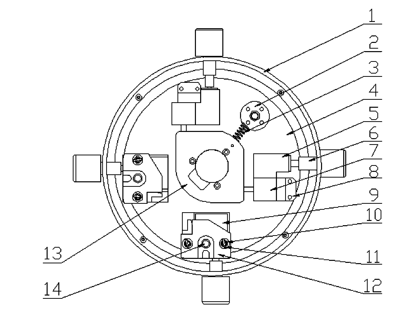
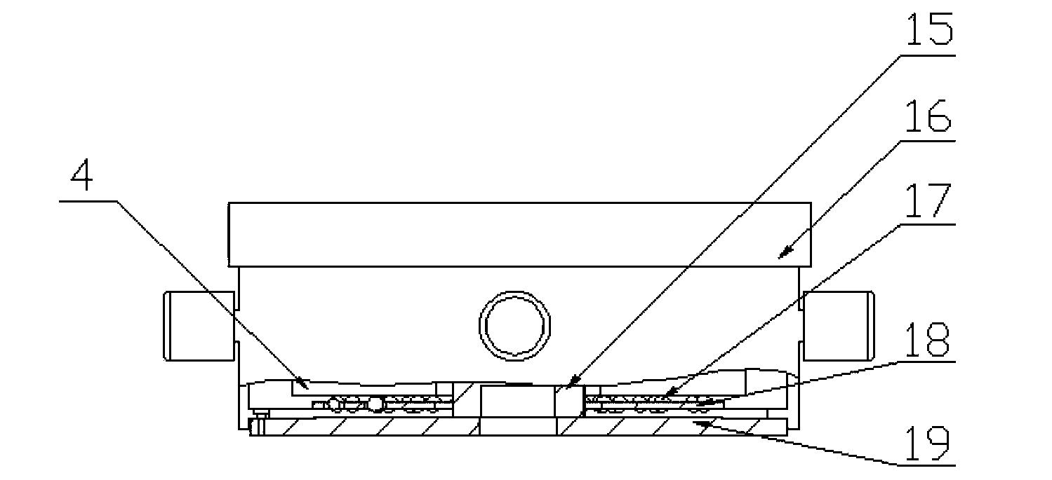
[0051] A self-aligning and leveling workbench for a high-precision cylindricity instrument, including a self-aligning device, a leveling device, a workbench shell 1, a fixed steel ball support 2, a self-aligning pre-tension spring 3, a middle mounting plate 4, and a middle Mounting plate fixing member 13, adjusting platform pressure column 15, self-aligning platform upper cover 16, center mounting plate bottom steel ball 17, self-aligning ball plate 18, self-aligning platform base 19, and cylindrical guide block 23.
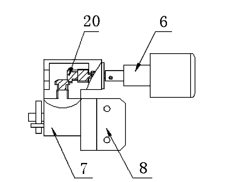
[0052] The centering device is composed of an adjusting hand wheel 6, a centering worm gear box 7, a centering worm gear box fixing seat 8, a bevel gear steering box 5, a centering feed head block 21, and a centering feed head 22 . The bevel gear steering box 5 is a metal rectangular parallelepiped with two bevel gears 20 that mesh with each other vertically. It is connected with the self-aligning worm gear box 7 by screws, and one of the bevel gears is connected to the worm of the self-aligning worm gear box 7 The shaft is connected, and the other bevel gear is coaxially connected with the adjusting hand wheel 6, and the rotation axis direction of the adjusting hand wheel 6 can be changed by 90° through the bevel gears meshing with each other. The self-aligning worm gear box 7 is a metal rectangular parallelepiped. Its side is fixedly connected with the side of the bevel gear steering box 5. The inside is a worm gear and a worm structure. The output end of the worm and a bevel gear in the bevel gear steering box 5 Coaxially connected, one side of the worm gear output shaft of the self-aligning worm gear box 7 is threaded to connect the self-aligning feed head 22, and a fixed rod is arranged on its side close to the self-aligning feed head 22, and the fixed rod extends into the adjusting The heart feeds into the gap of the head block 21. The self-aligning feed head 22 is a round rod with a thread at one end, and the material is stainless steel. Its threaded end is threaded with the worm wheel in the self-aligning worm gear box 7, and the other end is clamped by the self-aligning feed head clamp 21 . The self-aligning feed head clamp 21 is a rectangular block with two notches. The material is carbon steel. One of the notches is used to clamp the unthreaded end of the self-aligning feed head 22, and the other is used for the adjustment. The fixed rods on the center worm gear box 7 cooperate with each other, and the function is to prevent the centering feed head block 21 from rotating when the centering worm gear box 7 outputs rotation, and to ensure that the centering feed head 22 and the centering feed head are locked. The block 21 moves linearly along the worm gear shaft of the self-aligning worm gear box 7. The two self-aligning feed heads 22 respectively bear against the two sides of the middle mounting plate fixing member 13 that are 90° with each other. The adjusting hand wheel 6 is a metal stepped cylindrical shape, and the hand wheel is rolled with a pattern. It passes through a through hole on the workbench housing 1 and is coaxially connected with another bevel gear of the bevel gear steering box 5. The self-aligning worm gear box fixing seat 8 is a metal block with an "L" cross-section. The side of the self-aligning worm gear box fixing seat 8 is fixedly connected with the other side of the self-aligning worm gear box 7, and the self-aligning worm gear box fixing seat 8 The bottom surface is fixedly connected with the middle mounting plate 4.
[0053] The outer shell of the workbench 1 is a metal circular ring with 4 through holes evenly distributed on the outside. The material is aluminum alloy. It is fixedly connected to the base 19 of the self-aligning platform by screws.
[0054] The fixed steel ball support 2 is a stepped cylindrical shape, made of carbon steel, and is fixedly connected to the middle mounting plate 4 by screws.
[0055] The middle mounting plate 4 is made of stainless steel torus. It is placed on the bottom steel balls 17 of the 56 middle mounting plates. The two cylindrical guide blocks 23 at the bottom are placed in two symmetrical long notches on the spherical ball plate 18.
[0056] The middle mounting plate fixing member 13 is a stainless steel rectangular parallelepiped. Two non-adjacent corners are chamfered with different radii, and a through hole is opened at the center. It is sleeved on the upper part of the pressure column 15 of the adjusting platform. It is connected with the pressure column 15 of the adjusting platform by screws.
[0057] The self-aligning pre-tightening spring 3 is a tension spring, made of carbon spring steel wire, which connects and fixes the steel ball support 2 and the intermediate mounting plate fixing member 13, and has a certain pre-tightening force.
[0058] The self-aligning ball disk 18 is a metal circular ring, with four long holes evenly distributed on its outer side, and 56 circular holes on its surface. The size of the above-mentioned circular holes matches the diameter of the steel balls placed inside it. , Generally larger than the diameter of the steel ball. The spherical ball plate 18 is placed under the middle mounting plate 4. The direction of the four long holes of the spherical ball disk 18 corresponds exactly to the X and Y directions of the worktable, ensuring that the spherical ball disk 18 only moves linearly along the X and Y directions during the centering process without appearing Rotate.
[0059] Adjusting platform pressure column 15 is a stepped cylindrical shape, the material is stainless steel, the upper part is connected with the middle mounting plate fixing part 13 by screws, the middle mounting plate fixing part 13 is sleeved on the upper part of the adjusting platform pressure column 15, the bottom of the adjusting platform pressure column 15 and the centering The platform base 19 is fixedly connected by screws.
[0060] The base 19 of the self-aligning platform is a stainless steel stepped ring with 8 threaded holes evenly distributed on its outer side for threaded connection with the workbench housing 1. Two cylindrical guide blocks 23 are provided on its inner side. The cylindrical guide block 23 is cylindrical and made of plastic. It is placed in the other two symmetrical notches on the spherical ball disk 18, and is connected to the middle mounting disk 4 by screws.
[0061] The leveling device consists of a leveling worm gear box 9, a leveling pre-tensioning spring 10, a leveling pre-tensioning spring clamp 11, a leveling steel ball support 12, a leveling steel ball 14, an adjusting hand wheel 6 and a leveling inlet. Give the first 24 composition.
[0062] The leveling worm gear box 9 is a metal cuboid, and its interior is a worm wheel and a worm structure. Its worm is coaxially connected with the adjusting hand wheel 6, and the worm wheel is connected with the leveling feed head 24. The leveling feed head 24 is a stainless steel cylindrical rod with a pin at one end and a thread on the other end. The pin sinks into the rectangular groove at the bottom of the leveling steel ball support 12. The leveling steel ball support 12 is a stainless steel cuboid. It is installed on the leveling worm gear box 9. There is a circular groove in the center of the upper end surface, and two counterbores are opened on both sides of the circular groove. The leveling and pre-tightening spring clamp rod 11 for placing the leveling and pre-tightening spring 10 has a rectangular groove on the bottom surface for placing the bolt on the worm gear box leveling feed head 24. The leveling pre-tightening spring 10 is a tension spring, which is made of carbon spring steel wire. It connects the middle mounting plate 4 and the leveling steel ball support 12, and has a certain pre-tightening force. The leveling and pretensioning spring bar 11 is a stainless steel cylindrical bar, which is placed horizontally in two countersunk holes on the upper end of the leveling steel ball support 12, and one end of the leveling and pretensioning spring 10 is hung on the leveling and pretensioning spring clip. At the center of rod 11. The material of the leveling steel ball 14 is stainless steel, and is placed in a circular groove in the center of the upper end surface of the leveling steel ball support 12.
[0063] During the leveling process, the leveling worm gear box 9 converts the horizontal displacement into a displacement perpendicular to the middle mounting plate 4, so as to change the height against the leveling steel ball support 12 through the leveling on the two leveling devices The steel ball 14 and the leveling steel ball 14 on the fixed steel ball support 2 support the entire workbench to achieve leveling.
[0064] In the present invention, there are two centering devices and two leveling devices, which are installed symmetrically along the center line of the middle mounting plate, and are installed on the middle mounting plate 4 at an angle of 90°.
[0065] The upper cover 16 of the self-aligning platform is in the shape of a circular plate, made of stainless steel, and is placed on the surface of the three leveling steel balls 14.
[0066] The steel balls 17 at the bottom of the middle mounting plate are made of stainless steel, and there are 56 steel balls in total. They are placed in the round holes of the spherical ball plate 18 to make the middle mounting plate 4 roll on the balls to reduce friction during adjustment. When working, the parts to be tested are placed on the upper cover 16 of the centering adjustment platform. When adjusting the centering platform, operate the adjustment hand wheel 6, through the adjustment hand wheel 6, through the bevel gear steering box 5 and the centering worm gear box 7, so that the centering feed head 22 is along the centering feed head 22 axis It moves in a straight line, thereby driving the middle mounting plate 4 to move in the horizontal X and Y directions to achieve centering. When leveling the self-aligning platform, operate the adjustment hand wheel 6, through the adjustment hand wheel 6, the leveling worm gear box 9, so that the leveling feed head 24 moves linearly along the axis of the leveling feed head 24, thereby driving the adjustment The flat steel ball bearing 12 pitches to achieve leveling.
[0067] The present invention uses bevel gear steering box 5, self-aligning worm gear box 7 and self-aligning feed head 22 for centering, and uses bevel gears to convert the input and output angles of the worm gear box, and at the same time uses springs to give a certain pretension , The self-aligning displacement is transmitted through the rolling of the steel ball in the self-aligning ball disk, and the sliding friction is replaced by rolling friction, which reduces the resistance and reduces the error to a certain extent, thereby improving the centering accuracy. The present invention adopts the leveling worm gear box 9 and the leveling feed head 24 to convert the horizontal feed into the vertical upward displacement feed, thereby achieving leveling. The structural feature is to use a high-precision worm gear box with a large reduction ratio and a locking function, which replaces the conventional simple screw adjustment feed method, which improves the adjustment resolution, and at the same time uses the ball to cooperate with the center to improve the adjustment accuracy.

PUM

no PUM

Description & Claims & Application Information

We can also present the details of the Description, Claims and Application information to help users get a comprehensive understanding of the technical details of the patent, such as background art, summary of invention, brief description of drawings, description of embodiments, and other original content. On the other hand, users can also determine the specific scope of protection of the technology through the list of claims; as well as understand the changes in the life cycle of the technology with the presentation of the patent timeline. Login to view more.

Similar technology patents

Low-moisture low-variable serial saturation tower thermal CO transformation technology

ActiveCN102888253AShort transformation processReduce resistanceHydrogenCombustible gas catalytic treatmentDry gasMoisture
Owner:CHINA PETROCHEMICAL CORP +2

Classification and recommendation of technical efficacy words

  • Reduce resistance
  • Reduce mistakes

Terminal positioning track fitting method based on Bezier curve

ActiveCN102998684AReduce mistakesSatellite radio beaconingSatellite navigationFitting methods
Owner:XIAMEN YAXON NETWORKS CO LTD

Multifunctional road soil roadbed freezing and thawing circulating test device

ActiveCN101923085ASolving Elasticity ProblemsReduce mistakesRoadwaysEarth material testingTest measurementFrost
Owner:CCCC SECOND HIGHWAY CONSULTANTS CO LTD
Why Eureka
Try Eureka