Inertial navigation measurement method for pipeline center line

A technology of inertial navigation measurement and inertial navigation, which is applied in the field of inertial navigation measurement of the pipeline centerline to achieve the effect of saving maintenance costs and improving maintenance efficiency

Inactive Publication Date: 2014-04-02
PETROCHINA CO LTD
5 Cites 24 Cited by

AI-Extracted Technical Summary

Problems solved by technology

But it has not been applied to the...

Abstract

The invention provides an inertial navigation measurement method for a pipeline center line of a buried pipeline. An inertial navigation detection positioner is adopted for measurement, and is composed of a mobile carrier unit, an inertial measurement unit, an odometer wheel, a data storage unit, a data downloading and processing unit, a speed control unit, and a ground tracking positioning and power management unit. The method comprises the procedures: firstly setting parameters of a detection device; combining with a GPS system to complete initial coordinate setting; carrying out self-inspection of the device, and returning to zero; if being not completed, going back to set the parameters of the detection device; if being completed, mounting an inertial navigation system on a detector or other carriers; detecting and carrying out real-time data acquisition; completing the detection; calibrating a terminal position by the GPS system; downloading data, carrying out post treatment, and resolving center line data; carrying out error correction, and completing drawing of coordinates; and ending. The method can accurately draw out the three-dimensional coordinates, moving directions and displacement of the pipeline center line and even pipeline deformation.

Application Domain

Technology Topic

Image

  • Inertial navigation measurement method for pipeline center line
  • Inertial navigation measurement method for pipeline center line
  • Inertial navigation measurement method for pipeline center line

Examples

  • Experimental program(1)

Example Embodiment

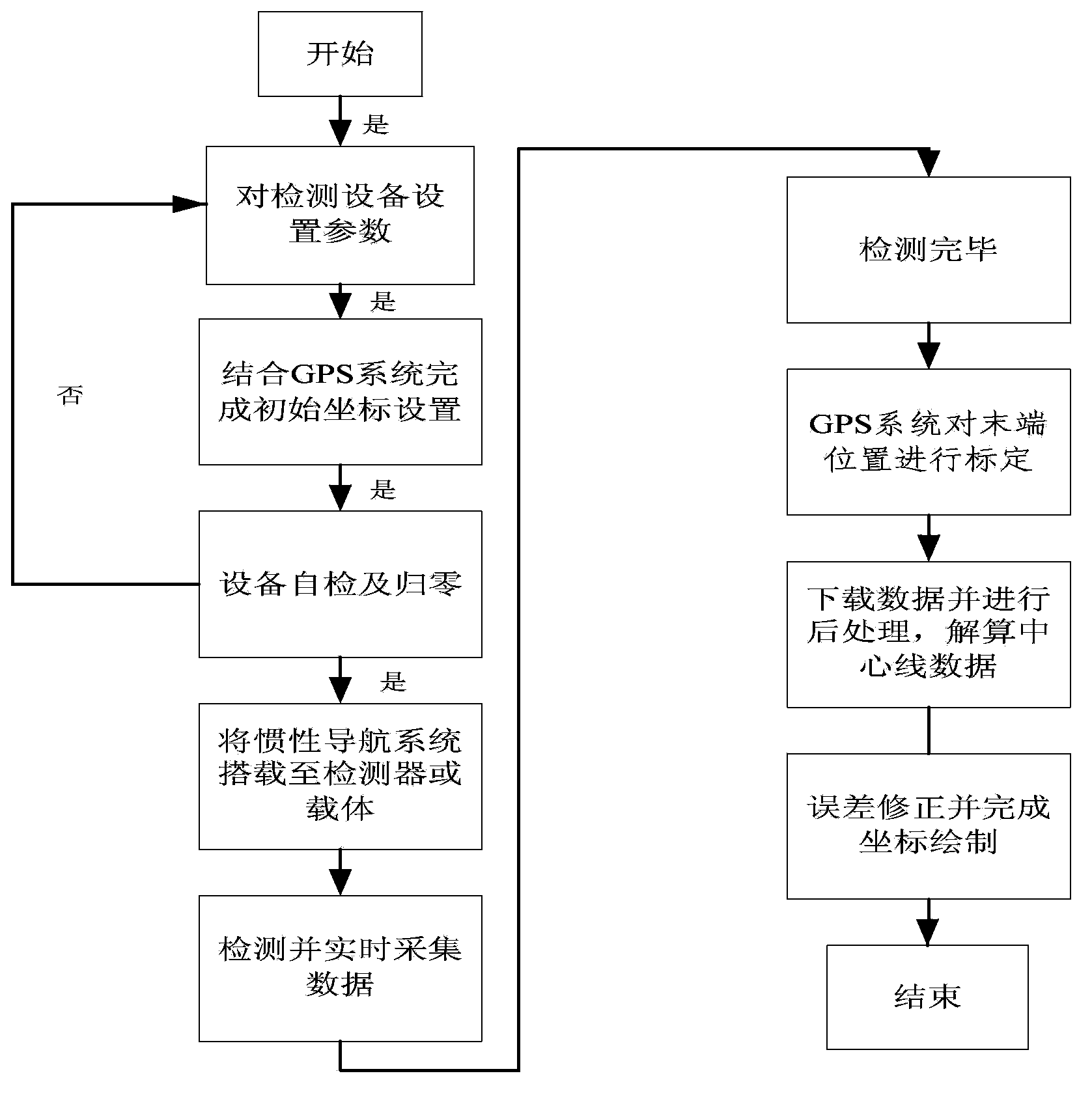
[0030] Example. The inertial navigation detection locator used for measurement is composed of a mobile carrier unit, an inertial measurement unit, a mileage wheel, a data storage unit, a data download and processing unit, a speed control unit, a ground tracking and positioning unit, and a power management unit. Its process is:
[0031] After the detection starts, set parameters for the detection equipment;
[0032] Combined with GPS system to complete the initial coordinate setting;
[0033] Equipment self-test and reset;
[0034] If it is not completed, turn back to setting parameters for the detection equipment; if completed, mount the inertial navigation system on the detector or other carriers;
[0035] Detect and collect data in real time;
[0036] The detection is completed;
[0037] The GPS system calibrates the terminal position;
[0038] Download the data and perform post-processing to solve the center line data;
[0039] Error correction and complete coordinate drawing;
[0040] Finish.
[0041] Several measurements were made on a pipeline using this measurement method. The first test holds the pipe at a uniform level for measurement. Before the formal inspection, first locate the center position of the starting point of the pipeline, the longitude is 116.731304, the latitude is 39.489336, the height is 25.0m, and the carrier speed is set at 1m/s. 3 degrees of lateral deflection to the carrier wheel. After the system self-test is completed, start the test. like image 3 is the motion trajectory diagram of the detector. from image 3 The middle and detection data can be obtained, the detector rotates about 2.5 circles in the pipeline, the advancing distance is 96.5946m, and the coordinates of the centerline of the entire pipeline are completely obtained. After the inspection, the length of the pipeline is measured, and the actual length is 96.6m, which is basically consistent with the test result of the detector.
[0042] Repeat the measurements a second time to compare the repeatability of the data. like Figure 4 , for the second full measurement data.
[0043] In the third test, the central part of the pipeline is settled by 0.25m, which is measured by this test method. like Figure 5 As shown, the third test track is compared with the first two test data. like Image 6Shown is the "longitude-height" curve of the three-test detector trajectory. It can be clearly seen from the figure that the difference between the middle height of the third measurement and the first two measurements is about 0.23m, which is consistent with the actual subsidence height of the pipeline, which proves that accuracy of this test method.
[0044] In this example, the centerline position, orientation, displacement and even the deformation of the buried pipeline can be measured and mapped.

PUM

no PUM

Description & Claims & Application Information

We can also present the details of the Description, Claims and Application information to help users get a comprehensive understanding of the technical details of the patent, such as background art, summary of invention, brief description of drawings, description of embodiments, and other original content. On the other hand, users can also determine the specific scope of protection of the technology through the list of claims; as well as understand the changes in the life cycle of the technology with the presentation of the patent timeline. Login to view more.

Similar technology patents

Classification and recommendation of technical efficacy words

  • Improve maintenance efficiency
  • Reduce maintenance costs

Monitoring method and terminal device of track circuit device

ActiveCN108501980AGuaranteed operational safetyImprove maintenance efficiencyVehicle route interaction devicesCase baseTerminal equipment
Owner:固安信通信号技术股份有限公司
Why Eureka
Try Eureka