Liquid core coupling surface plasma resonance imaging analyzer

A surface plasmon and analyzer technology, applied in the field of ion plasma resonance imaging analyzer, can solve problems such as excitation spot position offset, affecting imaging quality and analysis effect, multi-interface reflection interference, etc., to improve detection sensitivity and avoid light Distribution change, effect of reducing reflection interference

Active Publication Date: 2014-04-02
INST OF CHEM CHINESE ACAD OF SCI
View PDF8 Cites 2 Cited by
  • Summary
  • Abstract
  • Description
  • Claims
  • Application Information

AI Technical Summary

Problems solved by technology

[0005] 1. The shape of the prism is fixed, the excitation light cannot always be perpendicular to the incident surface of the prism, and the reflected light cannot always be perpendicular to the exit surface of the prism. When the light excitation angle changes, the position of the excitation spot will shift due to the light refraction effect , causing the light distribution to change, thus affecting the analysis effect; and it will also bring about the correction of the light excitation angle
[0006] 2. In order to reduce cost and facilitate use, the sensing film is mostly prepared on the substrate, and then pasted on the bottom surface of the prism with adhesive oil. The operation of adhesive oil is easy to generate air bubbles, which affects the imaging quality and analysis effect
[0007] 3. The incident surface of the excitation light and the prism, the reflected light and the exit surface of the prism cannot always be kept vertical, and the refractive index of the prism, adhesive oil and substrate is difficult to match ideally, which will bring reflection interference problems at multiple interfaces
[0008] All the above problems, in addition to the trouble of angle correction, will seriously affect the analysis quality of surface plasmon resonance and surface plasmon resonance imaging system

Method used


Image

  • Liquid core coupling surface plasma resonance imaging analyzer
  • Liquid core coupling surface plasma resonance imaging analyzer
  • Liquid core coupling surface plasma resonance imaging analyzer

Examples


Embodiment Construction

[0053] The specific implementation manners of the present invention will be described in detail below in conjunction with the accompanying drawings and typical embodiments. The following examples are used to illustrate the present invention, but are not intended to limit the scope of the present invention.

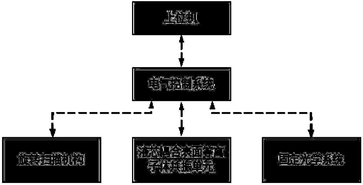
[0054] Such as figure 2 , 3 As shown, the present invention includes an instrument base plate 10, a rotating scanning mechanism 11, a liquid core coupled surface plasmon resonance unit 12, a fixed optical system 13, an electrical control system and a host computer. Wherein, the rotating scanning mechanism 11 and the fixed optical system 13 are all fixed on the instrument base plate 10 . The electrical control system is electrically connected with the rotating scanning mechanism 11 and the fixed optical system 13 at the same time, and can collect and control the image detected by the fixed optical system 13 and the light excitation angle detected by the rotating scanning...


PUM

PropertyMeasurementUnit
thicknessaaaaaaaaaa
thicknessaaaaaaaaaa

Abstract

The invention discloses a liquid core coupling surface plasma resonance imaging analyzer, and belongs to the technical field of testing instruments. The liquid core coupling surface plasma resonance imaging analyzer comprises a rotary scanning mechanism, a liquid core coupling surface plasma resonance unit, a fixed optical system, an electric control system and an upper computer. The position of the optical system is fixed during working; scanning for an optical excitation angle is realized by only rotating a sensing chip so as to ensure that excitation light is perpendicular to reflection light and an optical window, thus a position of a surface plasma resonance excitation spot is not changed all the time; meanwhile, the liquid core coupling surface plasma resonance imaging analyzer has the advantages that correction of the excitation light angle is not required, bonding oil does not need to be used, and multi-boundary reflection interference is reduced.

Description

technical field [0001] The invention belongs to the technical field of testing instruments, in particular to a surface plasmon resonance imaging analyzer. Background technique [0002] Surface plasmon resonance is a label-free, in situ and real-time interface analysis technique. The occurrence condition of surface plasmon resonance changes with the change of the refractive index of the sample on the sensing film-medium interface. Therefore, through surface plasmon resonance analysis, the refractive index and thickness information of the sample on the surface of the sensing film can be obtained, and the physical and chemical reactions on the surface of the sensing film can be monitored and analyzed. If the target molecule is bonded to the surface of the sensing film, Specific molecular interaction analysis can then be performed. Based on surface plasmon resonance technology, two types of analysis systems, surface plasmon resonance and surface plasmon resonance imaging, have...

Claims


Application Information

Patent Timeline
Patent Type & Authority Applications(China)
IPC IPC(8): G01N21/63
Inventor 许吉英陈义
Owner INST OF CHEM CHINESE ACAD OF SCI
Why Eureka
Try Eureka