P code catching method and device

A technology of acquisition device and P code, applied in the field of satellite navigation, can solve the problems of large uncertainty range of P code phase, susceptible to interference, low acquisition sensitivity, etc., to ensure environmental adaptability, reduce false alarm probability, and redundant resources. Large margin effect

Inactive Publication Date: 2014-04-02
BEIJING BDSTAR NAVIGATION CO LTD
View PDF4 Cites 16 Cited by
  • Summary
  • Abstract
  • Description
  • Claims
  • Application Information

AI Technical Summary

Problems solved by technology

[0004] In wartime and other conditions, because the civilian code is easily recognized by the enemy and is susceptible to interference, spoofing, etc., the civilian code signal of most satellites may be closed, so the existing way of guiding and capturing the P code cannot meet the actual needs. When , only the search engine that can directly capture the P code can realize the capture of the P code
[0005] However, due to the direct capture state, the time uncertainty is very large, generally tens or even hundreds of milliseconds, usually within 1 second, and the uncertainty range of the P code phase is large
At present, the general direct capture method adopts the method of circular correlation to capture the pseudo-code phase and serially search the carrier Doppler frequency, or uses FFT to search the carrier frequency and serially search for the pseudo-code phase. These two search strategies are too slow. The capture sensitivity is low, which directly affects the capture speed and sensitivity of the P code, and cannot meet the actual needs

Method used


Image

  • P code catching method and device
  • P code catching method and device

Examples


Embodiment Construction

[0032] In order to make the purpose, technical solution and advantages of the present invention more clear, the embodiments of the present invention will be described in detail below in conjunction with the accompanying drawings. It should be noted that, in the case of no conflict, the embodiments in the present application and the features in the embodiments can be combined arbitrarily with each other.

[0033] The steps shown in the flowcharts of the figures may be performed in a computer system, such as a set of computer-executable instructions. Also, although a logical order is shown in the flowcharts, in some cases the steps shown or described may be performed in an order different from that shown or described herein.

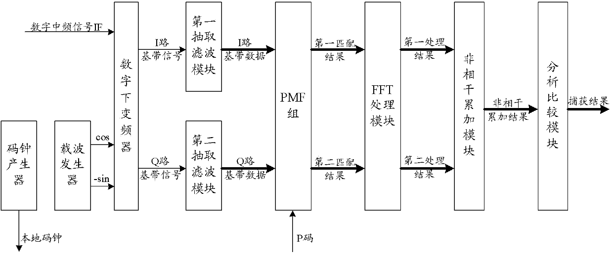
[0034] figure 1 It is a schematic diagram of the composition and structure of the P code capture device of the present invention, such as figure 1 As shown, it includes at least a code clock generator, a carrier generator, a digital down converter, a fir...


PUM


Abstract

The invention discloses a P code catching method and a P code catching device. The method comprises the following steps that IF (intermediate frequency) signals and local carrier signals from a carrier generator are multiplied, and I-Q two-path base band signals with rest Doppler frequency are obtained; the base band signals are extracted to obtain base band data to be processed, and the base band data to be processed is stored according to the sub segment; the local P code is used as a tap coefficient, each sub segment is respectively subjected to partial PMF to obtain accumulation results, and the code phase searching is completed; the filtering results after the PMF processing is subjected to buffer memory, in addition, fast FFT is respectively carried out, the frequency spectrum analysis is realized, and the frequency searching is completed; the accumulation according to points is carried out after the parallel model delivery is respectively carried out on the output results of the FFT processing, M point incoherent accumulation results are obtained, and the caught results are found, wherein the caught results include but are not limited to the maximum correlation value, the second correlation value, the frequency, the phase, the paragraph and the like. The method and the device provided by the invention have the advantages that a PMF and FFT combination mode is adopted, the P code catching sensitivity is improved, and the catching speed is obviously accelerated, so the requirements of actual signals are met.

Description

technical field [0001] The invention relates to satellite navigation technology, in particular to a P code acquisition method and device. Background technique [0002] Satellite navigation receivers used in vehicles and other environments do not have high requirements for dynamics, but have higher requirements for sensitivity than ordinary receivers. As the first step in the normal operation of the receiver, the fast capture engine has become a top priority to improve the capture sensitivity and speed up the capture. [0003] The Beidou satellite navigation system adopts QPSK modulation. Since the P code period is very long, the conventional P code acquisition method is to first capture the I branch civil code to obtain the time information in the navigation message. Due to the system time between the civil code and the P code Consistent, so after getting the accurate time from the civilian code, you can get a rough phase of the P code, and the phase error can be accurate t...

Claims


Application Information

Patent Timeline
Patent Type & Authority Applications(China)
IPC IPC(8): G01S19/30
CPCG01S19/30
Inventor 不公告发明人
Owner BEIJING BDSTAR NAVIGATION CO LTD
Why Eureka
Try Eureka