AP 1000 reactor core decoupling control system and control method

A technology of decoupling control and control system, applied in the field of AP1000 core control technology improvement, can solve the problems of load tracking flexibility limitation, reduce core response speed, weaken coupling effect, etc., to eliminate the influence of disturbance on controlled parameters , the effect of removing interlocking links and speeding up the response speed

Inactive Publication Date: 2014-04-02
XI AN JIAOTONG UNIV
View PDF3 Cites 6 Cited by
  • Summary
  • Abstract
  • Description
  • Claims
  • Application Information

AI Technical Summary

Problems solved by technology

However, all the control rods are used to control new problems: in order to weaken the coupling effect between the M rod group and the AO rod group, the AO rod group does not move when the M rod group is used, and the M rod group does not move when the AO rod group moves.

Method used


Image

  • AP 1000 reactor core decoupling control system and control method
  • AP 1000 reactor core decoupling control system and control method
  • AP 1000 reactor core decoupling control system and control method

Examples


Embodiment 1

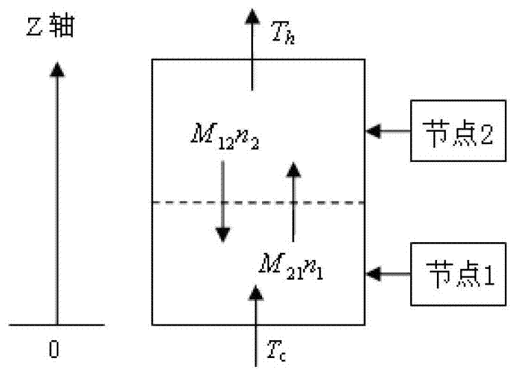
[0117] When the established core model is the core slow mode dual-node model, the dynamic process of the core when the decoupling control system and the original control system are used are respectively simulated when the core power drops from 100% FP to 90% FP . The initial conditions of the simulation are: beginning of life, equilibrium xenon, full power in hot state, AO loop is 0.001-0.02, temperature loop is 0.55-0.83. The simulation process assumes that the coolant inlet temperature remains constant at 280.7°C. Simulation results such as Figure 6 shown. From Figure 6 (a) It can be obtained that when the original control system is used, the core power fluctuates repeatedly between 180s and 320s, and the system does not reach stability until after 320s, which is caused by the coupling of M rods and AO rods. After adopting the decoupling control system of the present invention, the system can reach stability in 200s. Therefore, the decoupling control system of the pre...

Embodiment 2

[0119] When the established core model is a core fast-mode dual-node model, and the decoupling control system and the original control system are respectively simulated, the core power is calculated according to 12-3-6-3 (100%FP-70%FP- 100%FP) mode for daily load tracking of the core dynamic process. The initial conditions of the simulation are: beginning of life, equilibrium xenon, full power in hot state, AO loop is 0.001-0.02, temperature loop is 0.55-0.83. The simulation process assumes that the coolant inlet temperature remains constant at 280.7°C. Simulation results such as Figure 7 shown. From Figure 7 (a) and (b), it can be obtained that after adopting the decoupling controller, the power control effect is better and close to the target value in the process of load tracking. From Figure 7 (c) and (d) it can be obtained that after using the decoupling controller, the variation of AO value is smaller and can always be kept within the adjustment band, so the contr...


PUM


Abstract

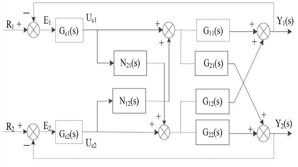
The invention provides an AP 1000 reactor core decoupling control system and control method; the control system comprises an M rod control system connected with a reactor core transfer function model, an AO rod control system, and a decoupling control system connected with the M rod control system and the AO rod control system and further connected with a reactor core model; the reactor core transfer function model feeds back cooling agent average temperature signals and nuclear power signals to the M rod control system and feeds back axial power distribution signals to the AO rod control system; the M rod control system inputs M rod group movement rod positions to the decoupling control system; the AO rod control system inputs AO rod group movement rod positions to the decoupling control system; the decoupling control system inputs the M rod group movement rod positions and the AO rod group movement rod positions, which are compensated, to the reactor core model. The system and the method not only can ensure the response speed of the system, but also can eliminate coupling effects of two rod groups.

Description

technical field [0001] The invention belongs to the technical improvement field of AP1000 core control, and in particular relates to an AP1000 core decoupling control system and a control method. Background technique [0002] In the past few decades, the world's nuclear power technology has been developing continuously, and its safety has made great progress. In addition, the operation and control methods of the world's nuclear power units have also been continuously developed and improved. After the Fukushima accident in Japan, China stipulated that newly built nuclear power units must meet the safety standards of the third generation of nuclear power, among which AP1000 is currently the main reactor type established by China. It can be seen that AP1000 units will develop rapidly in China in the future. [0003] AP1000 adopts passive safety system, which effectively improves the safety of the unit. The reactor control mode of the existing AP1000 nuclear power unit is cont...

Claims


Application Information

Patent Timeline
IPC IPC(8): G05B13/04
Inventor 赵福宇陈丽
Owner XI AN JIAOTONG UNIV
Why Eureka
Try Eureka