servo motor

A servo motor and motor shaft technology, applied in the field of servo motors, can solve the problems of reducing production efficiency, increasing the diameter of the shaft, reducing the rigidity of the casing, etc., and achieve the effects of increasing manufacturing costs, shortening the length and prolonging the service life

Active Publication Date: 2016-03-30
NINGBO TENGLONG OUTDOOR IMPLEMENT
View PDF7 Cites 15 Cited by
  • Summary
  • Abstract
  • Description
  • Claims
  • Application Information

AI Technical Summary

Problems solved by technology

[0003] 1) Since the fan is located at the end far away from the output shaft of the motor, and the encoder in the servo motor is also installed at this end and is coaxial with the fan, therefore, when the fan starts or stops, the torque value on the shaft is very high , if the diameter of the shaft is small, it will cause the shaft to be twisted, which will inevitably increase the diameter of the shaft, so that the specification of the encoder will also increase, and the corresponding manufacturing cost will greatly increase;
[0004] 2) In addition, in the couplings in the prior art, the output shaft of the motor and the input shaft of the oil pump are usually connected through a standard coupling. Therefore, the length of the output shaft of the motor extending out of the casing is relatively long. The rigidity of the output shaft of the motor is poor, and the output shaft of the motor is prone to breakage; at the same time, the space occupied by the entire servo motor is relatively large;
[0005] 3) In addition, since the sleeve body and the outer ring are of a split structure, the connection between the two and the positional relationship between the two must be considered during assembly. Therefore, there are many parts and troublesome assembly, which greatly reduces production efficiency; At the same time, the design of the split structure also greatly reduces the rigidity of the casing

Method used


Image

  • servo motor
  • servo motor
  • servo motor

Examples


Embodiment Construction

[0027] The present invention will be described in further detail below in conjunction with the accompanying drawings and specific embodiments.

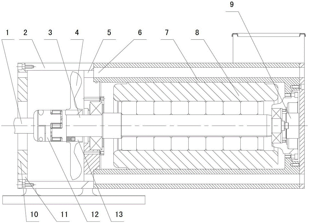
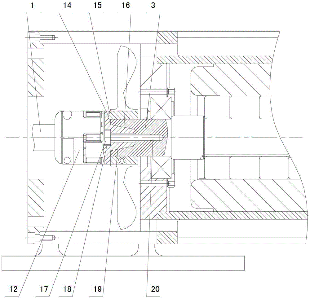
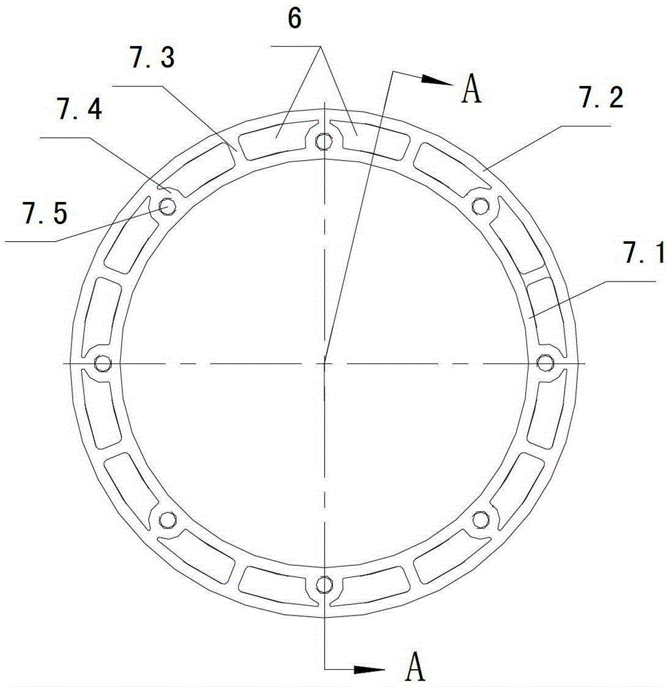
[0028] Depend on Figure 1 ~ Figure 4 As can be seen from the shown structural diagram of the servo motor of the present invention, it includes a motor 8, an encoder 9, a fan 4, an air guide sleeve 7 and a shaft coupling connecting the motor shaft 3 and the input shaft 1 of the working part (in this embodiment, the working Component is an oil pump), the motor 8 is located in the wind guide sleeve 7, and the end of the motor shaft 3 extending out of the motor housing is the output end, and the other end is the tail end, and the encoder 9 is installed on the tail end of the motor shaft 3. The fan 4 is fixedly connected to the output end of the motor shaft 3, the coupling is an elastic coupling 12 and is located between the output end of the motor shaft 3 and the end face of the input shaft 1 of the working part, the elastic coupling 12 ...


PUM


Abstract

The invention discloses a novel servomotor which comprises a motor (8), an encoder (9), a fan (4), an air deflector sleeve (7) and a coupler used for connecting a motor shaft (3) with an operation component input shaft (1); the motor (8) is positioned in the air deflector sleeve (7); one end, extending out of a motor housing, of the motor shaft (3) is an output end, and the other end of the motor shaft is a tail end; the encoder (9) is mounted at the tail end of the motor shaft (3); the fan (4) is fixedly connected to the output end of the motor shaft (3); the coupler is an elastic coupler (12) and positioned between the output end of the motor shaft (3) and the end surface of the operation component input shaft (1); one part of the elastic coupler (12) is connected with the operation component input shaft (1), and the other part of the elastic coupler (12) is connected with the motor shaft (3). After the structure is adopted, not only can the breakage of the shaft at the fan not be caused, but also the manufacturing cost is not increased.

Description

technical field [0001] The invention relates to the technical field of motors, in particular to a servo motor. Background technique [0002] Servo motors have been widely used in various industries. At present, some servo motors do not have a fan, and their heat dissipation adopts natural cooling, while some have a fan, which uses the cold air brought by the fan to take away the heat of the heating parts and accelerate the cooling speed. The servo motor with fan in the prior art, such as the patent "Heat Dissipation Structure of Servo Motor" published on the patent website with the publication number CN202997836U, includes a sleeve set on the outside of the motor housing, and the sleeve The outer end of the fan is provided with a fan installation mechanism, the fan installation mechanism is equipped with a fan, and at least one heat dissipation channel for the air flow generated by the fan is provided between the sleeve body and the motor housing; in addition, the motor out...

Claims


Application Information

Patent Timeline
Patent Type & Authority Patents(China)
IPC IPC(8): H02K9/06H02K11/20H02K7/00H02K5/20H02K11/21
Inventor 刘坚
Owner NINGBO TENGLONG OUTDOOR IMPLEMENT
Why Eureka
Try Eureka