Differential mechanism type track combine-harvester gearbox

A technology for combine harvesters and differentials, applied in harvesters, agricultural machinery and implements, applications, etc., can solve the problems of braking power loss, life reduction, gear damage, etc., to improve life and reliability, reduce Effects of wear and life reduction

Active Publication Date: 2014-04-09
JIANGSU UNIV
View PDF6 Cites 17 Cited by
  • Summary
  • Abstract
  • Description
  • Claims
  • Application Information

AI Technical Summary

Problems solved by technology

[0003] However, there is a big problem at present. When one side of the track is braked, it will produce complete sliding friction against the ground when turning, which will seriously damage the paddy field soil; when it is turning, the track on the braking side will cause soil accumulation. As a result, it will cause difficulty in steering and insufficient fuel combustion. At the same time, due to the demand for large feed combine harvesters in the market, under the same chassis aspect ratio, increasing the weight of the whole machine will make steering more difficult; field operations It is necessary to fine-tune the travel route. The traditional unilateral braking steering system adopts the point brake steering method for fine-tuning, which will cause serious wear and tear on the internal friction plate and greatly reduce the service life.
When turning, there is a braking power loss on the inner track, and the outer side needs more power from the engine. Once the load increases, the resistance of the track on one side increases, which will cause the engine to stall
[0004] Patent ZL03245493.9 discloses a walking steering device, which realizes steering and straight travel by braking the left and right clutch gears and the parallel planetary gear mechanism. This structure can realize the function of in-situ steering, but it cannot be directly used in actual field operations, because It uses the clutch shaft to complete the switching between steering and straight travel. Once the left and right half shafts are combined in reverse, it will cause serious damage to the cogs on the clutch shaft, and it will stop for a while after turning in situ, which is harmful to field operations. poor fluency
[0005] Patent ZL240640024088.7 discloses a dual-flow steering mechanism. Steering input power and straight-moving power converge through the planetary wheels on both sides, which can smoothly complete the conversion of steering and straight travel. However, it is a dual-flow structure that requires an additional separate power to complete it. Steering, the power distribution of the existing combine harvester is already very tight, there is no redundant power distribution to the steering mechanism, and the price is relatively expensive
[0006] Patent application 241324140240.4 discloses a single-flow idler-shaft-type in-situ steering mechanism, which achieves the effect of adding an idler wheel to achieve the reverse effect by sliding the dual gear. It adopts the method of mechanical sliding gear, which is quite laborious and increases the intensity of field work

Method used


Image

  • Differential mechanism type track combine-harvester gearbox
  • Differential mechanism type track combine-harvester gearbox
  • Differential mechanism type track combine-harvester gearbox

Examples


Embodiment 1)

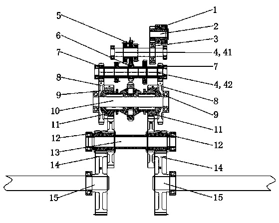
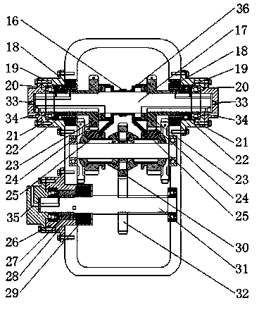
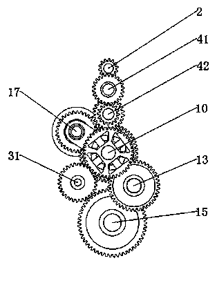
[0030] See Figure 1 to Figure 3, the differential gear type crawler combine harvester transmission box of the present invention; comprise box body, comprise power input shaft 2, three-speed transmission gear shift shaft 4, differential gear shaft 10, steering control shaft 17, differential gear The control shaft 31, the power output shaft 13, and the two power output half shafts 15 located at the lower part of the power output shaft 13 and respectively connected to the two ends of the power output shaft 13 through gears, and the gear transmission mechanism and hydraulic pressure that are arranged on each shaft and mesh with each other Control System.

[0031] The shift shaft 4 of the third-gear transmission device includes a first third-gear transmission shift shaft 41 and a second third-gear transmission shift shaft 42 .

[0032] The power input shaft 2 is provided with a power input gear 1, and the first triple gear 5 and the third gear input gear 3 are arranged on the shi...


PUM


Abstract

The invention belongs to the field of agricultural machinery, and particularly relates to a differential mechanism type track combine-harvester gearbox. The differential mechanism type track combine-harvester gearbox comprises a box body, wherein a power input shaft, a three-gear speed changing device gear shifting shaft, a differential mechanism shaft, a steering control shaft, a differential mechanism control shaft, a power output shaft, two power output half shafts, a gear drive mechanism and a hydraulic control system are sequentially arranged in the box body, the two power output half shafts are located on the lower portion of the power output shaft and connected with the two ends of the power output shaft through gears respectively, and the gear drive mechanism and the hydraulic control system are arranged on all the shafts and meshed with each other. According to the differential mechanism type track combine-harvester gearbox, few braking power losses exist, steering can be more easily achieved, the steering radius is smaller, field operation can be more easily conducted, the turnover probability is greatly lowered, large-radius or pivot steering of a vehicle can be achieved by braking a differential mechanism gear, and the operation is easier and more convenient; no friction plate needs to be used in the leftward-rightward fine adjustment, losses of the friction plate are greatly reduced, the service life of the gearbox is further prolonged, and the reliability of the gear box is further improved.

Description

technical field [0001] The invention belongs to the field of agricultural machinery, and relates to a gearbox transmission system of a single-stream crawler-type combine harvester, in particular to a steering mechanism of a crawler-type harvester gearbox using a differential. Background technique [0002] At present, the steering mechanism of domestic crawler combine harvesters mainly adopts the principle of single-flow unilateral braking steering, which uses the separation of the intermediate clutch shaft to brake one side of the crawler belt to complete the steering, through the control of the brakes on the left and right half shafts of the clutch. Complete turns of various radii. [0003] However, there is a big problem at present. When one side of the track is braked, it will produce complete sliding friction against the ground when turning, which will seriously damage the paddy field soil; when it is turning, the track on the braking side will cause soil accumulation. ...

Claims


Application Information

Patent Timeline
Patent Type & Authority Applications(China)
IPC IPC(8): A01D69/06
Inventor 李耀明姜晓春徐立章唐忠
Owner JIANGSU UNIV
Why Eureka
Try Eureka