Press-filter unidirectional continuous plate pulling device

A one-way continuous, filter press technology, applied in the direction of filtration separation, separation methods, chemical instruments and methods, etc., can solve the problems of general efficiency, low work efficiency, unreliable performance, etc., and achieve simple structure and movement, saving pull board time, design reasonable effect

Active Publication Date: 2014-04-09
ZHEJIANG HUAZHANG TECH
View PDF7 Cites 2 Cited by
  • Summary
  • Abstract
  • Description
  • Claims
  • Application Information

AI Technical Summary

Problems solved by technology

[0002] The plate pulling device used in the filter press can pull the filter plate in the filter press. The conventional automatic plate pulling structure has the following types: 1) Ordinary reciprocating automatic plate pulling: through a pair of manipulators on both sides of the main beam. Reciprocating pull plate, this structure is simple, the action is reliable, but relatively low efficiency
2) One-time pull plate: Equidistant chains are installed on the handles of all filter plates, and one end of the chain is fixed on the pressing plate, and a large-stroke oil cylinder or a moving oil cylinder drives the pressing plate to move, and then drags the filter plates in turn to realize automatic Pull plate, this structure has high efficiency, but it must cooperate with a large stroke, and generally the distance between filter plates is relatively small, and the length space is seriously wasted
3) Three times of pulling plates: divide all filter plates into three groups, add a middle reinforcing plate, start to pass through, press the plate as the first group of pulling plates, and pass through the middle reinforcing plate to make the second group of pulling plates, the second group of pulling plates The plate will drive the third group to move, but it does not pull the plate, and the third set of plate is pulled back through the middle reinforcing plate; the length and space of the three pulling plates are relatively saved, but the efficiency is average, and the structure is also generally responsible.
[0003] Now some patents of plate pulling devices have been disclosed. For example, on August 1, 2012, the Chinese patent with publication number CN102614693A discloses a plate pulling device for a filter press. The plate pulling device includes The running device arranged on the guide rail of the filter press, the pull plate seat set on the running device, the push plate claw and the pull plate claw are arranged on the pull plate seat, and the adjustable seat plate is arranged on the pull plate seat, The adjustable seat plate can move relative to the plate-drawing seat, the push plate claw is rotatably connected to the adjustable seat plate, and the plate-drawing claw is rotatably connected to the adjustable seat plate; during actual use In this case, the pulling device is prone to jamming
Another example is that the date of authorization announcement is April 02, 2008, and the announcement number is CN201042640Y in the Chinese patent, which discloses a filter press puller, which includes two I shafts on the puller box. The push plate and the pull plate are installed on the top, the two ends of the spring are hung on the lower part of the push plate and the pull plate, and the hook is installed on the right side of the pull plate box. The openings of the plate box are all set at the bottom, and the bearings are installed on the two II shafts above the guide rail, and the I wheel and II wheel are installed on the two III shafts below the guide rail. Since the two ends of the spring hook the pull plate and the push plate, when The pull plate and the push plate are linked by springs, and the performance is not reliable enough
Another example is that the authorized announcement date is August 25, 2010, and the announcement number is CN201558590U in the Chinese patent, which discloses a device for grouping and pulling apart filter plates of a filter press. The filter plate of the filter machine is divided into several groups, each group consists of several filter plates to form the middle filter plate, and each group is provided with a drive filter plate, the lower end of the handle installed on the middle filter plate is linear, and the lower end of the handle installed on the drive filter plate is a boss There are chain rings installed on both sides of the handle of the middle filter plate and the handle of the driving filter plate, and the chain rope or rope is connected through the chain ring, and the plate puller is connected to the boss of the drive filter plate handle, and the plate puller reciprocates to pull the filter plates apart; Since the plate puller needs reciprocating motion to pull the filter plates apart, continuous work cannot be achieved, resulting in low work efficiency
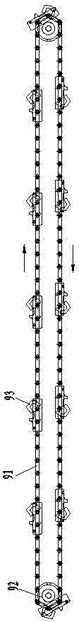
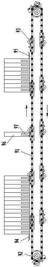
[0004] To sum up, there is currently no one-way continuous plate pulling device for filter presses with simple structure, reasonable design, convenient use, reliable performance, and high working efficiency.

Method used


Image

  • Press-filter unidirectional continuous plate pulling device
  • Press-filter unidirectional continuous plate pulling device
  • Press-filter unidirectional continuous plate pulling device

Examples


Embodiment Construction

[0025] The present invention will be further described in detail below in conjunction with the accompanying drawings and examples. The following examples are explanations of the present invention and the present invention is not limited to the following examples.

[0026] Example.

[0027] see Figure 1 to Figure 9 , the one-way continuous plate pulling device of the filter press in this embodiment includes a chain 91, two sprockets 92 and several manipulators 93, wherein the chain 91 is installed on the two sprockets 92, and the sprockets 92 can drive the chain 91 rotates, and several manipulators 93 in the present embodiment are evenly fixed on the chain 91, and the quantity of manipulators 93 among the present invention is usually 6-20.

[0028]The manipulator 93 in this embodiment includes a frame body 1, an upper limit block 2, a lower limit block 3, an actuator 4, an execution pin shaft 5, an execution torsion spring 6, a control element 7, a control pin shaft 8, a cont...


PUM

PropertyMeasurementUnit
angleaaaaaaaaaa

Abstract

The invention relates to a press-filter unidirectional continuous plate pulling device, and aims to provide a press-filter unidirectional continuous plate pulling device with a reliable performance and high work efficiency to fill the technical blank. The device comprises a chain, two chain wheels and a plurality of mechanical arms; and is characterized in that: each mechanical arm comprises a frame, an upper limiting block, a lower limiting block, an executing member, an executing pin shaft, an executing torsion spring, a control member, a control pin shaft, and a control torsion spring; the executing member comprises an executing rod, a hooked hand, and an top pressing head; the upper limiting block, the lower limiting block, the executing pin shaft and the executing torsion spring are all fixed on the frame; the control member comprises a top torsion spring section, a position limiting section, a filter plate top pressing section, and a control section; a rotation hole is arranged on the joint part between the top torsion spring section and the position limiting section; the control pin shaft and the control torsion spring are both arrange on the frame; and the control member is movably connected to the control pin shaft through the rotation hole. The press-filter unidirectional continuous plate pulling device can unidirectionally, continuously and rapidly pull the filter plates in a press-filter and finishes the cake-unloading operation of the press-filter.

Description

technical field [0001] The invention relates to a plate pulling device, in particular to a one-way continuous plate pulling device for a filter press, which is used for separating the filter plates in the filter press so that the filter cake between the filter plates falls off. Background technique [0002] The plate pulling device used in the filter press can pull apart the filter plate in the filter press. The conventional automatic plate pulling structures are as follows: 1) Ordinary reciprocating automatic plate pulling: through a pair of manipulators installed on both sides of the main beam. The reciprocating pull plate has a simple structure and reliable action, but relatively low efficiency. 2) One-time pull plate: Equidistant chains are installed on the handles of all filter plates, and one end of the chain is fixed on the pressing plate, and a large-stroke oil cylinder or a moving oil cylinder drives the pressing plate to move, and then drags the filter plates in tu...

Claims


Application Information

Patent Timeline
Patent Type & Authority Applications(China)
IPC IPC(8): B01D25/32
Inventor 钟新钢沈家纯阮宇科盛利
Owner ZHEJIANG HUAZHANG TECH
Why Eureka
Try Eureka