Method for manufacturing heat radiator
A manufacturing method and radiator technology, applied in manufacturing tools, heat exchange equipment, applications, etc., can solve problems such as difficulty in correction, deformation of fins, and increased load on friction stirring devices, and achieve the effect of improving flatness
- Summary
- Abstract
- Description
- Claims
- Application Information
AI Technical Summary
Problems solved by technology
Method used
Image

Examples
no. 1 approach )
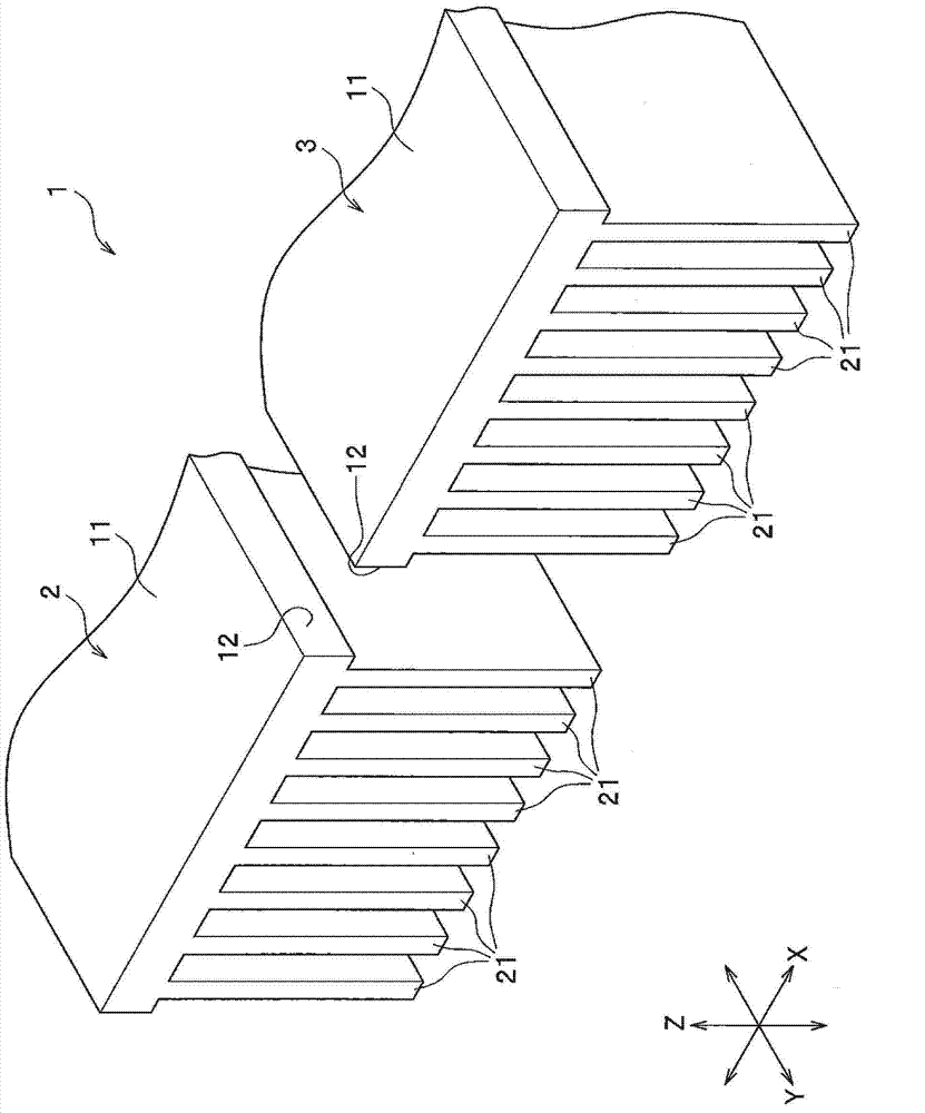
[0054] Embodiments of the present invention will be described in detail with reference to the drawings. Such as figure 1As shown, in the heat sink manufacturing method of this embodiment, the heat sink 1 is manufactured by performing friction stir welding of the first metal member 2 and the second metal member 3 . Such as figure 1 As shown, the X axis represents the width direction of the first metal member 2, the Y axis represents the depth direction, and the Z axis represents the height direction. In addition, "up and down" in the following description is used for convenience of description, and has nothing to do with the use state of the heat sink.
[0055] The first metal member 2 is composed of a plate-shaped bottom plate 11 and a plurality of fins 21 arranged side by side on the lower surface of the bottom plate 11 . The fins 21 are formed vertically with respect to the bottom plate 11 on the lower surface of the bottom plate 11 . In addition, the fins 21 are arrange...
no. 2 approach )
[0071] Next, a second embodiment of the present invention will be described. In the manufacturing method of the heat sink of the second embodiment, it is different from the first embodiment in that the plate thickness of the bottom plate 11 is large.
[0072] Such as Figure 4 As shown, the first metal member 2 is composed of a bottom plate 11 and a plurality of fins 21 arranged side by side on the lower surface of the bottom plate 11 . The structure of the fins 21 is the same as that of the first embodiment. In the bottom plate 11, the end surface 12 which opposes the 2nd metal member 3 is comprised from the outer end surface 12a, the inner end surface 12b, and the intermediate surface 12c.
[0073] The outer end surface 12 a is provided on the lower side (fin 21 side) of the bottom plate 11 . The inner end surface 12 b is provided on the upper side of the bottom plate 11 . In addition, the inner end surface 12 b is retracted (Japanese: Setback) relative to the outer end ...
no. 3 approach )
[0090] Next, a third embodiment of the present invention will be described. In the manufacturing method of the heat sink of the third embodiment, it is different from the first embodiment in that the first metal member 2 and the second metal member 3 are joined to the back contact 31A in the joining step.
[0091] like Figure 9 As shown in (a), the first metal member 2 is composed of a bottom plate 11 and a plurality of fins 21 arranged side by side on the lower surface of the bottom plate 11 . The structure of the fins 21 is the same as that of the first embodiment. In the bottom plate 11, the end surface 12 which opposes the 2nd metal member 3 is comprised from the outer end surface 12a, the inner end surface 12b, and the intermediate surface 12c.
[0092] The outer end surface 12 a is provided on the upper side of the bottom plate 11 . The inner end surface 12b is provided on the lower side of the bottom plate. In addition, the inner end surface 12b is retracted relati...
PUM
 Abstract
Description
Claims
Application Information
 - Generate Ideas
- Intellectual Property
- Life Sciences
- Materials
- Tech Scout
- Unparalleled Data Quality
- Higher Quality Content
- 60% Fewer Hallucinations
Browse by: Latest US Patents, China's latest patents, Technical Efficacy Thesaurus, Application Domain, Technology Topic, Popular Technical Reports.
© 2025 PatSnap. All rights reserved.Legal|Privacy policy|Modern Slavery Act Transparency Statement|Sitemap|About US| Contact US: help@patsnap.com