A deburring device for shaft parts

A technology for removing burrs and parts, which is applied in grinding/polishing safety devices, machine tools suitable for grinding the edge of workpieces, grinding machines, etc., which can solve the problem that cleanliness requirements cannot meet standards, affect the service life of shock absorbers, and burrs cannot be effective Deburring and other problems, to achieve the effect of improving burr removal efficiency, reducing work intensity and realizing automation

Inactive Publication Date: 2016-05-18
SICHUAN NINGJIANG SHANCHUAN MACHINERY
View PDF6 Cites 2 Cited by
  • Summary
  • Abstract
  • Description
  • Claims
  • Application Information

AI Technical Summary

Problems solved by technology

However, for shaft parts such as the internal parts of the shock absorber - the piston rod assembly, after the end face of this type of assembly has been riveted or spot riveted, the burrs generated have not been effectively removed or the removal effect is not good, and often fall off ( Sticking to the parts) and half-shedding iron filings remain on the parts, resulting in the failure to meet the cleanliness requirements, thus affecting the service life of the shock absorber
[0003] In addition, the riveting of the piston rod assembly of the shock absorber is manually removed, which is inefficient

Method used


Image

  • A deburring device for shaft parts
  • A deburring device for shaft parts
  • A deburring device for shaft parts

Examples


Embodiment 2

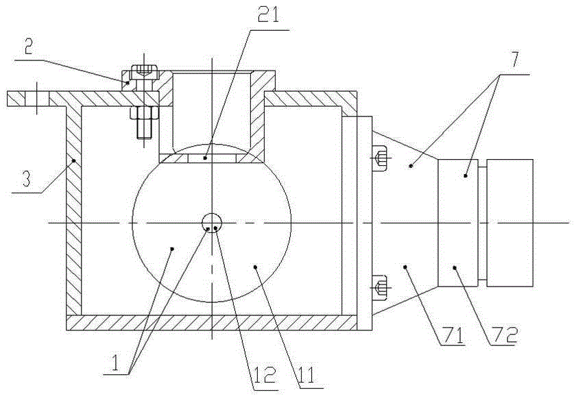
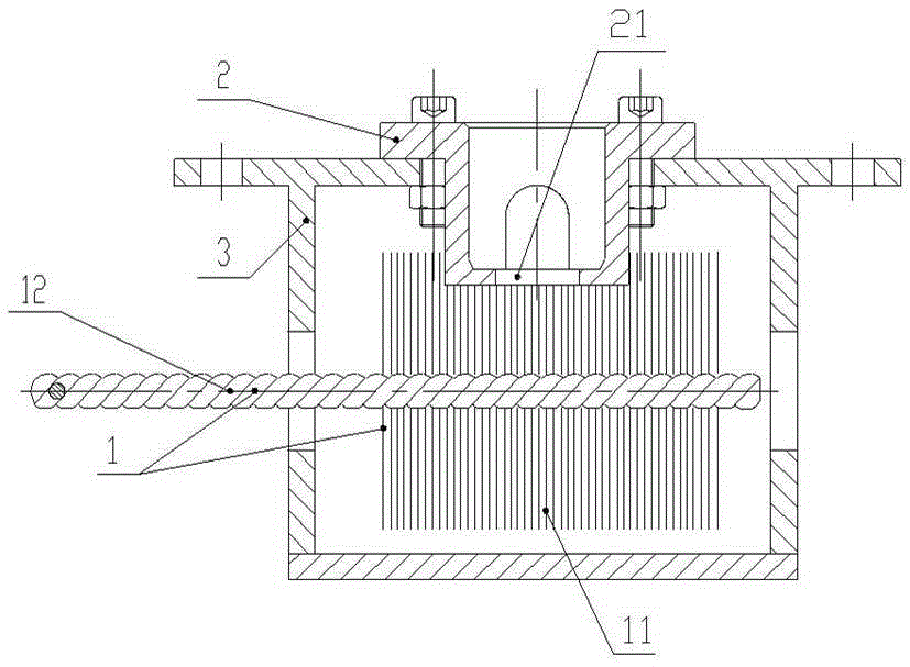
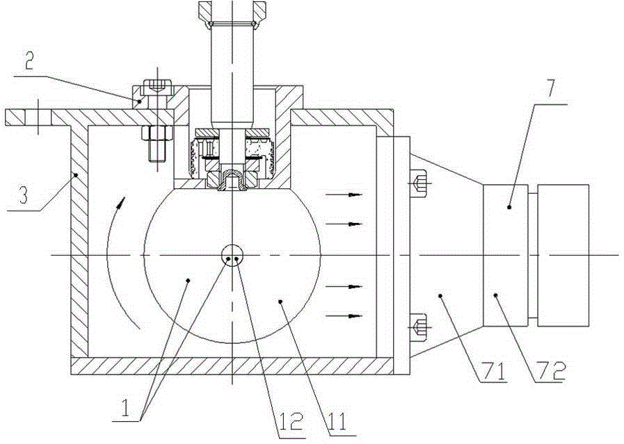
[0033] This embodiment is on the basis of embodiment 1, as Figure 4 and as Figure 5 As shown, the above-mentioned fixed base 2 includes a mounting cylinder 23 for mounting parts and a mounting plate 22 for fixing the mounting cylinder 23, wherein the mounting plate 22 is connected to the outer wall of the mounting cylinder 23 and fixed on the top of the box body 3, which is preferably The mounting cylinder 23 is molded integrally. In practice, it can also be two separate bodies connected together by means of welding or fasteners; the first through hole 21 is set at the bottom of the mounting cylinder 22 .

[0034] The above-mentioned dust suction device interface 7 is arranged on one side of the box body 3, and the dust suction device interface 7 is composed of a hollow conical cylinder 71 and a cylinder 72, and the end of the conical cylinder 71 with a smaller diameter is connected to the cylinder 72 The end with a larger diameter is fixed on the box body 3 through a lock ...

Embodiment 3

[0037] On the basis of Embodiment 1 or Embodiment 2, the brush head of the above-mentioned wire brush 1 includes bristles 11 and the front end of a brush handle 12 connected to the bristles 11, the above-mentioned bristles 11 are wavy stainless steel wires with a diameter less than 0.5mm, and the above-mentioned brush handle 12 is a spiral iron wire, which is formed by spirally winding an iron wire with a diameter of 2mm to 4mm. In practical applications, the diameter of the bristles 11 and the diameter of the handle 12 can be adjusted according to specific needs.


PUM


Abstract

The invention discloses a shaft part burr removal device which comprises a wire brush (1), a box body (3), a fixing base (2) for fixing parts and a dust-suction device port (7) for discharging iron scraps. The fixing base (2) is arranged at the top end of the box body (3), and a first through hole (21) communicated with the inside and the outside of the box body (3) is formed in the fixing base (2); a second through hole is formed in one lateral face of the box body (3), a brush head of the wire brush (1) is located in the box body (3), and the tail end of a brush handle (12) extends out of the box body (3) through the second through hole; the dust-suction device port (7) is formed in the box body (3) and communicated with the box body (3). According to the shaft part burr removal device, burrs are removed in a negative pressure environment, the burrs generated by rise riveting of shaft parts can be effectively removed, the brushed iron scraps can be timely sucked under the effect of a dust-suction device, the dropped iron scraps can be effectively prevented from being left in the box body or on the shaft parts, and the shaft part burr removal device has the advantages of being good in burr removal effect, convenient to use and the like.

Description

technical field [0001] The invention relates to a deburring device, in particular to a deburring device for shaft parts. Background technique [0002] At present, devices such as copper brushes and wire brushes are mainly used to remove burrs after assembly parts are processed. Devices such as copper brushes and wire brushes can effectively eliminate burrs generated externally after assembly parts are processed. However, for shaft parts such as the internal parts of the shock absorber - the piston rod assembly, after the end face of this type of assembly has been riveted or spot riveted, the burrs generated have not been effectively removed or the removal effect is not good, and often fall off ( Sticking to the parts) and semi-shedding iron filing impurities remain on the parts, resulting in the failure to meet the cleanliness requirements, thus affecting the service life of the shock absorber. [0003] In addition, the riveting of the piston rod assembly of the shock absor...

Claims


Application Information

Patent Timeline
Patent Type & Authority Patents(China)
IPC IPC(8): B24B9/00
CPCB24B9/00B24B55/06
Inventor 陈涛
Owner SICHUAN NINGJIANG SHANCHUAN MACHINERY
Why Eureka
Try Eureka