Automobile brake energy storing-releasing driving device and automobile brake energy storing-releasing driving method

A technology of automobile braking and driving devices, applied in the direction of auxiliary driving devices, power devices, control devices, etc., can solve the problems of limited efficiency, high energy loss, and many on-board equipment, so as to prolong the service life, increase the cylinder volume, The effect of reducing volume

Active Publication Date: 2014-04-09
王力丰
View PDF6 Cites 10 Cited by
  • Summary
  • Abstract
  • Description
  • Claims
  • Application Information

AI Technical Summary

Problems solved by technology

[0005] Electric hybrid vehicles have made some progress in terms of energy saving and emission reduction, but there are many problems: (1) In addition to the vehicle engine, its power system needs to add generators, storage batteries, motors or generators/motors, which occupy a relatively large portion of the vehicle. Large space and weight; (2) The electric energy of the storage battery comes from the external energy source and the on-board engine, which still consumes energy and fuel to a considerable extent; (3) The efficiency in recovering and utilizing the kinetic energy lost when the car brakes and decelerates is limited, Because a) If a special on-board generator is used to "collect" the electric energy generated by the wheel rotation (cutting the magnetic field line) during braking and deceleration and store it in the storage battery, and then use another special on-board motor to start the car, When accelerating, the electric energy obtained from the battery drives the wheels to rotate, and th...

Method used


Image

  • Automobile brake energy storing-releasing driving device and automobile brake energy storing-releasing driving method
  • Automobile brake energy storing-releasing driving device and automobile brake energy storing-releasing driving method
  • Automobile brake energy storing-releasing driving device and automobile brake energy storing-releasing driving method

Examples


Embodiment 1

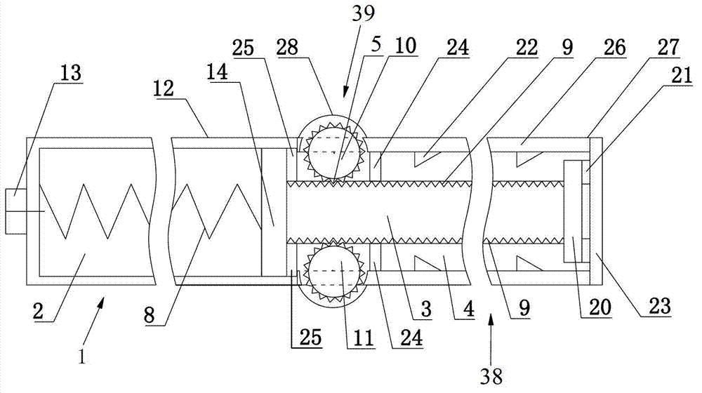
[0044] Such as figure 1 , Figure 5 and Figure 6 As shown, this embodiment describes a vehicle brake energy storage-energy release driving device 34, including:

[0045] The spring cylinder 1 includes a cylinder wall 12 forming a cylinder cavity, a piston 14 that is slidably engaged with the inside of the cylinder wall 12, and a spring that is connected between the piston 14 and the end of the spring cylinder 1 and whose direction of elasticity is parallel to the sliding direction of the piston 14. A coil spring 8, a gas medium 2 is arranged in the cylinder chamber;

[0046] The translation part 38 includes one end connected to the piston 14, a double-sided tooth column 3 with rack slots 9 respectively distributed on opposite sides along the sliding direction, and accommodating the double-sided tooth column 3 to slide therein The translation part shell 27;

[0047] The rotating part 39 is two gears 10 and 11 that mesh and match with the rack groove 9 corresponding to the ...

Embodiment 2

[0065] This embodiment records a vehicle brake energy storage-energy release driving method of the above-mentioned device, including the following steps:

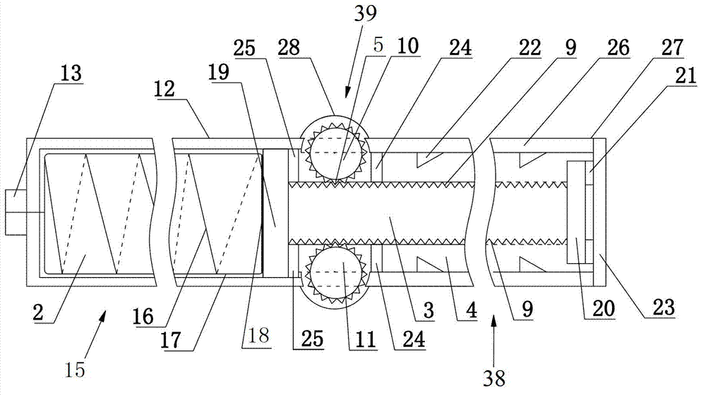
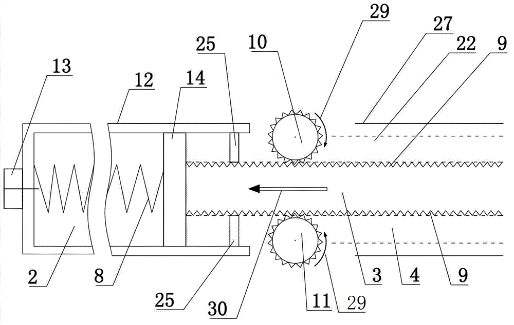
[0066] When the car brakes and decelerates, the car transmission shaft-wheel rotation causes the two gears of the car brake energy storage-energy release driving device to rotate in the first rotation direction 29 through the input transmission system, and the two gears and the double-sided gear column of the translation part The meshing makes the double-sided tooth column of the translation part drive the piston 14, 19 to translate 30 in the first direction, compress the gas medium 2 of the spring cylinder 1, 15 and the coil spring 8, 16, so that the device stores energy, and at the same time, the automobile system Slow down;

[0067] When the car starts to accelerate, the compressed gas medium 2 in the spring cylinders 1, 15 and the coil springs 8, 16 release energy and expand, so that the pistons 14, 19 drive the double-...


PUM


Abstract

The invention discloses an automobile brake energy storing-releasing driving device which comprises a cylinder with a spring, a translation portion and a rotation portion. The cylinder with the spring comprises a cylinder wall, a piston and the spiral spring, a cylinder cavity is formed by the cylinder wall, the piston is in sliding fit with the inner side of the cylinder wall, the spiral spring is connected among the piston and the ends of the cylinder, the direction of elasticity of the spiral spring is parallel to the sliding direction of the piston, and gaseous media are arranged in the cylinder cavity or are arranged in a built-in rubber capsule cavity of the cylinder; the translation portion comprises a double-side toothed column and a shell of the translation portion, one end of the double-side toothed column is connected with the piston, rack grooves are formed in two opposite sides of the double-side toothed column along the sliding direction, and the double-side toothed column is arranged in the shell of the translation portion; the rotation portion comprises two gears, and the two gears are meshed with the double-side toothed column from the two opposite sides of the double-side toothed column, are respectively connected with a brake system of an automobile by input transmission systems and are connected with a hybrid power device by output transmission systems. The invention further discloses an automobile brake energy storing-releasing driving method. The automobile brake energy storing-releasing driving device and the automobile brake energy storing-releasing driving method have the advantages that energy of the automobile can be saved, and emission of the automobile can be reduced.

Description

technical field [0001] The invention relates to the technical field of automobile energy saving, in particular to an automobile brake energy storage-energy release drive device and method. Background technique [0002] The automobile industry started in 1885 when the Germans Daimler and Benz assembled the internal combustion engine on a tricycle and developed to today. An ordinary car is composed of tens of thousands of parts, and its power, transmission, suspension, steering, braking, electrical appliances, and body systems are all modern technologies. For example, the mechanical transmission in the transmission system, through the combination and matching of various gears, realizes the mutual transformation of the vertical axis and the horizontal axis, the transformation of high speed and low speed and the magnitude of torque, the transformation of the direction of motion, and the mutual transformation of one group and multiple groups of rotation... It can Transformation ...

Claims


Application Information

Patent Timeline
IPC IPC(8): B60T17/00B60K25/10
CPCB60T1/10F03G1/00B60K6/10B60Y2400/164F03G1/02Y02T10/62
Inventor 王力丰
Owner 王力丰
Why Eureka
Try Eureka