
A single-drive material moving mechanism

A single-drive, sliding zone technology, applied in the direction of conveyor objects, transportation and packaging, etc., can solve the problems that affect the overall speed of the equipment, cannot adapt to the development trend, lead wires move into the blanking part, etc., to shorten the action response time and reduce the handling Process, the effect of increasing the speed of movement

Active Publication Date: 2016-03-09
大连佳峰自动化股份有限公司
View PDF10 Cites 0 Cited by
  • Summary
  • Abstract
  • Description
  • Claims
  • Application Information

AI Technical Summary

Problems solved by technology

However, neither of these two conveying methods can make the lead wires move into the blanking part completely, and it is necessary to install a material transfer mechanism on the conveying mechanism to push the side end faces of the lead wires so that the leads can be completely moved into the blanking part.
This method of directly adding the material transfer mechanism to the conveying mechanism must add a conveying action to the last conveying device, and the previous conveying device will be affected, which will prolong the conveying cycle and affect the overall speed of the equipment. Unable to adapt to the development trend of higher and higher UPH requirements in semiconductor chip loading equipment

Method used


Image

  • A single-drive material moving mechanism
  • A single-drive material moving mechanism
  • A single-drive material moving mechanism

Examples


Embodiment Construction

[0012] The present invention is described below in conjunction with accompanying drawing and specific embodiment:

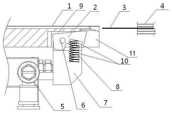
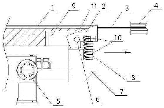
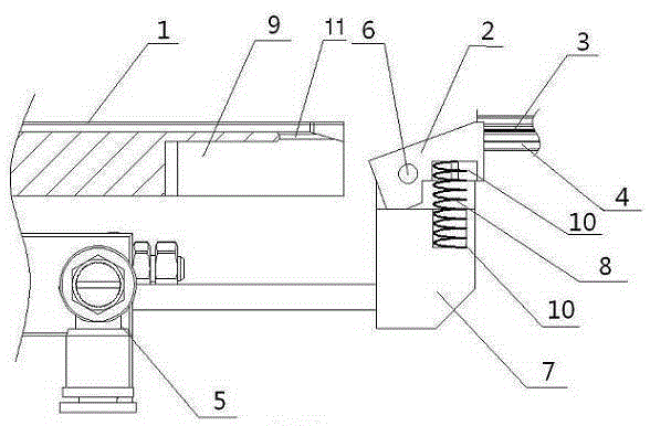
[0013] figure 1 It is a schematic diagram of the present invention when the cylinder piston rod is in a contracted state. A single-drive material shifting mechanism, including a lead track 1 for the lead wire 3 to move, a material box 4 for the lead wire 3 to move in, and a track gap 9 that is open below and behind the lead track 1 and located in the track gap. In the free sliding area 11 at the rear, a pushing block 2 is provided in the track gap 9, and the pushing block 2 is slidably connected in the track gap 9 and the free sliding area 11; the initial position of the pushing block 2 of the present invention is just in this track gap 9 in. One side of push block 2 is connected with push block fixed block 7 by pin 6 rotation, and the other side of push block 2 is connected with push block fixed block 7 by stage clip 8; More specifically, between push block 2 ...


PUM


Abstract

A single-drive material moving mechanism comprises a leading wire rail for a leading wire to move and a material box for the leading wire to be moved into. The rear end of the leading wire rail is provided with a rail notch, the lower portion and the rear portion of the rail notch are both open, a pushing block is arranged in the rail notch and is connected in a sliding mode in the rail notch, one side of the pushing block is connected with a shaft of a pushing block fixing block, the other side of the pushing block is connected with the pushing block fixing block through a compression spring, the lower portion of the leading wire rail is fixedly provided with a cylinder, and the pushing block fixing block is fixedly connected with the piston rod end of the cylinder. When the highest point of the pushing block is located outside the rail notch, the largest height of the pushing block is slightly higher than the upper plane of the leading wire and makes contact with the end face of the side edge of the leading wire. The single-drive material driving mechanism is simple in structure; due to the fact that the material moving mechanism is separated from a transportation mechanism, when a last conveying device returns, the cylinder can operate, one transportation process is reduced, motion response time is shortened, and the moving speed of the equipment is increased.

Description

technical field [0001] The invention relates to a pneumatic mechanism, in particular to a single-drive material moving mechanism. It is mainly suitable for wire transfer in the semiconductor (integrated circuit) packaging industry. Background technique [0002] In the semiconductor (integrated circuit) packaging industry's semiconductor chip loading equipment, the leads bonded to the chip need to be moved from the track part to the blanking part, and the leads need to be completely moved into the blanking part. [0003] The movement of the lead wire on the lead wire track will be realized by a conveying mechanism, and the existing conveying mechanism is mainly divided into two categories, the crochet form and the jaw form. Wherein, the crochet hook form is to use the positioning hole or the gap in the lead wire to insert the crochet needle into it and push the lead wire to move; the clamping claw form is to use the jaw to clamp the edge of one side of the lead wire to move ...

Claims


Application Information

Patent Timeline
Patent Type & Authority Patents(China)
IPC IPC(8): B65G47/82
Inventor 杜绍明王云峰金元甲
Owner 大连佳峰自动化股份有限公司
Learn More