Backlight source and display device
A technology of backlight source and light source, applied in electric light source, lighting device, light source fixing and other directions, can solve the problems of reducing the assembly efficiency of the backlight source and sinking, and achieve the effect of improving the display quality of the picture, the assembly efficiency and the picture quality.
- Summary
- Abstract
- Description
- Claims
- Application Information
AI Technical Summary
Problems solved by technology
Method used
Image

Examples
Embodiment 1
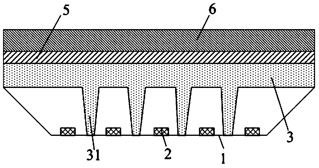
[0026] This embodiment provides a backlight, such as figure 2 As shown, it includes a backplane 1, a light source 2 and a diffusion plate 3. The light source 2 is arranged on the surface of the backplane 1, the diffusion plate 3 and the surface of the backplane 1 are parallel to each other, and the diffusion plate 3 is arranged on the backplane 1. On the side with the light source 2 and opposite to the light source 2 , a support column 31 is provided between the diffuser plate 3 and the back plate 1 , and the support column 31 and the diffuser plate 3 are made of the same material and integrally formed.
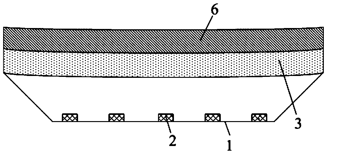
[0027] Wherein, the support column 31 and the diffuser plate 3 are integrally formed by injection molding, and the support column 31 extends along a direction perpendicular to the diffuser plate 3 to the surface of the back panel 1 where the light source 2 is disposed. Such as figure 1 As shown, the shape of the backplane 1 is an inverted trapezoid. During assembly, the dif...
Embodiment 2
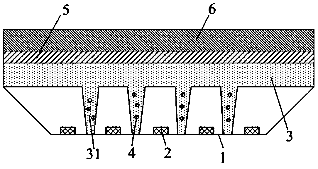
[0035] This embodiment provides a backlight source. The difference from Embodiment 1 is that image 3 As shown, on the basis of Embodiment 1, in this embodiment, luminescent particles 4 are added to the material forming the support column 31 , and the luminescent particles 4 can emit light when irradiated by the light source 2 . Wherein, the luminescent particles 4 are made of rare earth elements such as neodymium or europium. These materials obey the anti-Stokes effect, that is, under the illumination of the light source 2, after the luminescent center of these materials absorbs two or more photons, it undergoes non-radiative relaxation to reach the luminescent energy level, and the energy level transitions to the ground state that is Can emit a visible photon. By adding luminescent particles 4 , the support column 31 itself becomes a light source, thereby reducing the brightness difference between the support column 31 and other parts of the diffusion plate 3 and improving ...
Embodiment 3
[0038] This embodiment provides a backlight source. The difference from Embodiment 1-2 is that, for example Figure 4 As shown, a reflective sheet 7 is also arranged between the back plate 1 and the diffuser plate 3. The reflective sheet 7 has a through hole in the area corresponding to the light source 2. The light source 2 shoots to the diffuser sheet 3 through the through hole, and the support column 31 The free end is in contact with the reflector 7.
[0039]The reflective sheet 7 is arranged close to the backplane 1, and the arrangement of the reflective sheet 7 enables the light irradiated by the light source 2 to the direction of the backplane 1 to be reflected by the reflective sheet 7 to the diffusion plate 3, thereby improving the utilization rate of the light. Thereby further improving the picture quality.
[0040] Other structures of the backlight in this embodiment are the same as those in Embodiment 2, and will not be repeated here.
[0041] Beneficial effects ...
PUM
 Abstract
Description
Claims
Application Information
 - Generate Ideas
- Intellectual Property
- Life Sciences
- Materials
- Tech Scout
- Unparalleled Data Quality
- Higher Quality Content
- 60% Fewer Hallucinations
Browse by: Latest US Patents, China's latest patents, Technical Efficacy Thesaurus, Application Domain, Technology Topic, Popular Technical Reports.
© 2025 PatSnap. All rights reserved.Legal|Privacy policy|Modern Slavery Act Transparency Statement|Sitemap|About US| Contact US: help@patsnap.com