Circuit fault detection method, circuit fault detection system and controller

A technology for circuit faults and detection methods, applied in the field of circuits, can solve the problems such as the failure of the charger capacitor voltage to establish, the damage of surrounding devices, and the failure of the detection scheme, so as to achieve the effects of fast and effective detection, timely protection, and increased device cost.

Active Publication Date: 2014-04-09
HUAWEI DIGITAL POWER TECH CO LTD
View PDF3 Cites 18 Cited by
  • Summary
  • Abstract
  • Description
  • Claims
  • Application Information

AI Technical Summary

Problems solved by technology

The inventor of the present invention found in the process of research and practice of the prior art that the detection method of the prior art can only report a fault under specific working conditions, that is, it can only be effective after the output capacitor voltage is established, but the detection process If the protection is not proper, it is easy to cause the fault to expand and cause damage to the surrounding devices.
If the

Method used


Image

  • Circuit fault detection method, circuit fault detection system and controller
  • Circuit fault detection method, circuit fault detection system and controller
  • Circuit fault detection method, circuit fault detection system and controller

Examples


Embodiment 1

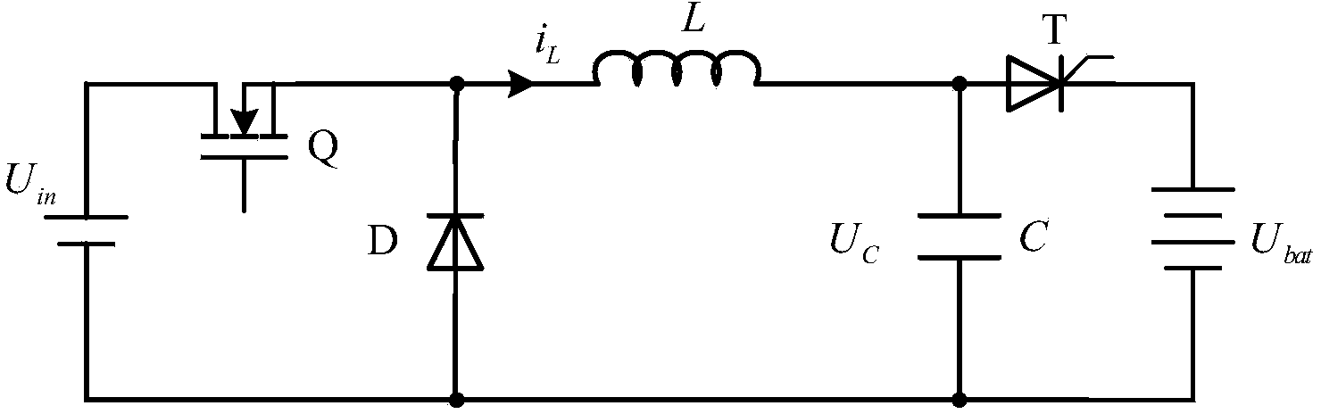
[0038] An embodiment of the present invention provides a circuit fault detection method. For the convenience of description, the description will be made from the perspective of the first controller in the circuit detection system. For example, the first controller may specifically be a digital signal processor (DSP, Digital Signal Processor). Wherein, the circuit may be a step-down conversion circuit (BUCK circuit), and the BUCK circuit may also include a second controller, and the second controller may specifically be a complex programmable logic device (CPLD, Complex Programmable Logic Device) . The BUCK circuit can be applied to electronic devices such as chargers. The following will take the application of this circuit on a charger as an example to describe in detail.

[0039] For details, please refer to figure 1 , figure 1is a schematic diagram of the BUCK circuit. It should be noted that the charger has the following three modes: stop mode, soft start mode and ru...

Embodiment 2

[0049] In order to better understand the above solution, the above technical solution will be described in detail below with a specific application example, wherein the first controller may specifically be a digital signal processor (DSP, Digital Signal Processor). Specifically, the second controller may be a complex programmable logic device (CPLD, Complex Programmable Logic Device), and the electronic device may be a charger.

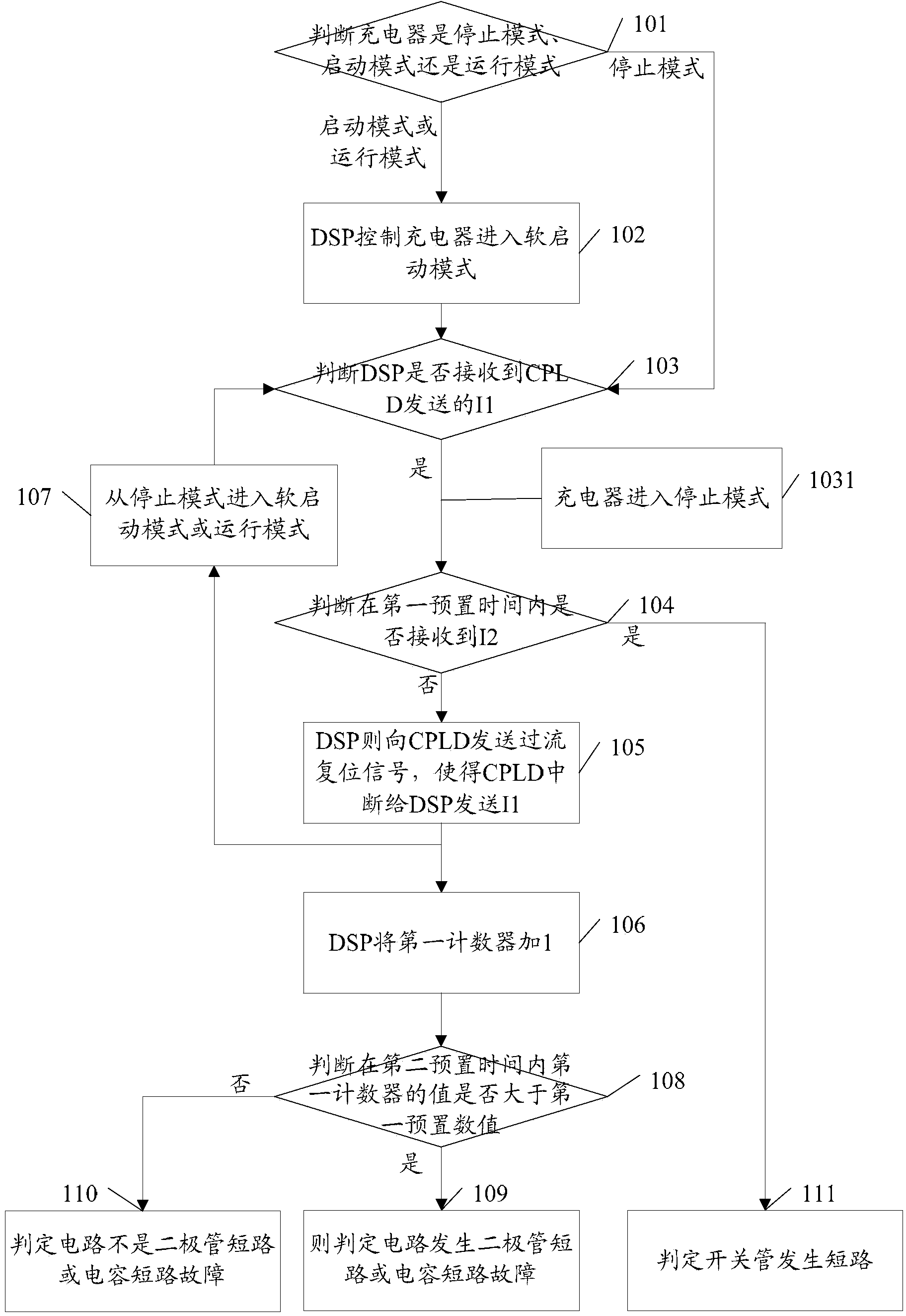
[0050] see figure 2 , the details can be as follows:

[0051] 101. Determine whether the operation mode of the charger is stop mode, start mode or run mode, if the charger is in stop mode, perform step 102, and if the charger is in start mode or operation mode, perform step 103;

[0052] 102. If the charger is in the stop mode, the DSP controls the charger to enter the soft start mode, and execute step 103;

[0053] 103. Determine whether the DSP has received the I1 sent by the CPLD;

[0054] If received, execute step 104.

[0055] 1031. When the...

Embodiment 3

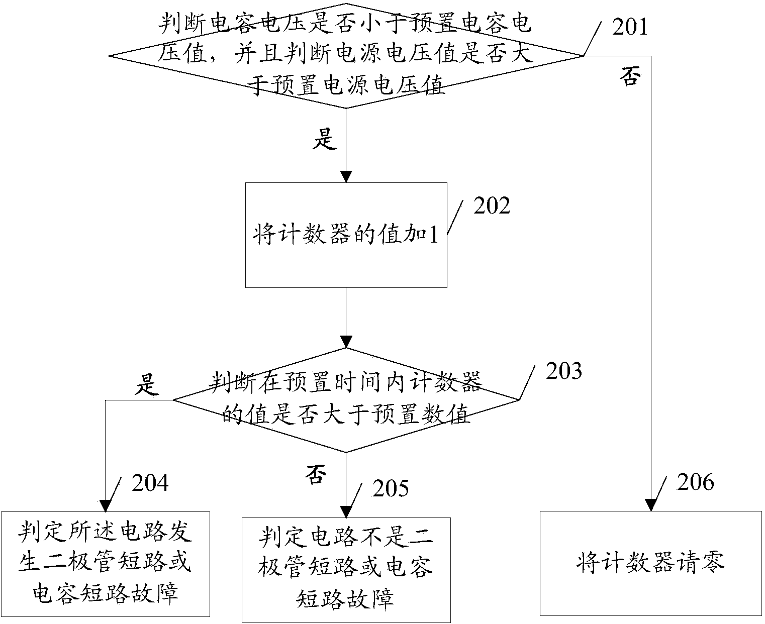
[0070] In this embodiment, it is judged whether a diode short-circuit or a capacitor short-circuit fault occurs in the circuit by judging the capacitor voltage and the power supply voltage. In the operation mode, when the first controller receives the overcurrent signal sent by the second controller, it can execute the following: steps, see image 3 :

[0071] 201. Determine whether the capacitor voltage is less than the preset capacitor voltage value, and determine whether the power supply voltage value is greater than the preset power supply voltage value;

[0072] If the capacitor voltage is less than the preset capacitor voltage value and the power supply voltage is greater than the preset power supply voltage value, step 202 is executed. If the capacitor voltage is not less than the preset capacitor voltage value, or the circuit voltage value is not greater than the preset circuit voltage value, step 206 is executed.

[0073] 202. If the capacitor voltage is less than t...


PUM


Abstract

The embodiment of the invention discloses a circuit fault detection method, a circuit fault detection system and a controller. According to the method disclosed by the embodiment of the invention, fault detection is carried out by making use of repeated and cyclic behavior characteristics of a charger after a free-wheeling diode or a capacitor is short-circuited when electronic equipment is in a soft start or operation mode, and fault detection is carried out by making use of the characteristics of capacitor voltage and battery voltage in the operation process of the electronic equipment. According to the embodiment of the invention, different detection schemes are adopted according to different characteristics of the electronic equipment before and after startup, effective detection can be carried out under various operation conditions without increasing the device cost, and false report or missing report does not occur; and over-current signal detection is adopted in the embodiment of the invention to timely perform a wave sealing action, a device can be timely protected during fault detection, the fault coverage is not enlarged, damage to other adjacent devices can be avoided, and the detection is quick and effective.

Description

technical field [0001] The invention relates to the field of circuits, in particular to a circuit fault detection method, system and controller. Background technique [0002] At present, the step-down conversion circuit BUCK circuit is widely used in various DC-to-DC step-down conversion occasions. Its circuit is simple and the output current ripple is small, and it is widely used in chargers. Among them, high-power chargers, especially in the scenario where multiple modules operate in parallel and share battery packs, are particularly important to detect device faults. If the fault can be accurately located and reported, and the faulty module can be quickly cut off from the system, it can effectively Avoid affecting the operation of the entire parallel system. [0003] The method for detecting the short circuit of the residual diode or the output capacitor in the BUCK circuit in the prior art is to judge whether a short circuit fault occurs by identifying a sudden drop in ...

Claims


Application Information

Patent Timeline
IPC IPC(8): G01R31/28G01R31/02H02H7/12
Inventor 孔雪娟庹鸿王术
Owner HUAWEI DIGITAL POWER TECH CO LTD
Why Eureka
Try Eureka