Inductor and manufacturing method thereof
A technology of inductance components and manufacturing methods, which is applied in the directions of electrical components, inductance/transformer/magnet manufacturing, transformer/inductor cores, etc., can solve the problems of insufficient coil interior, pressurization, and coil insulation coverage damage.
- Summary
- Abstract
- Description
- Claims
- Application Information
AI Technical Summary
Problems solved by technology
Method used
Image

Examples
no. 1 Embodiment approach
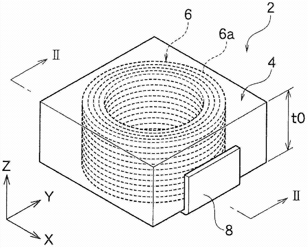
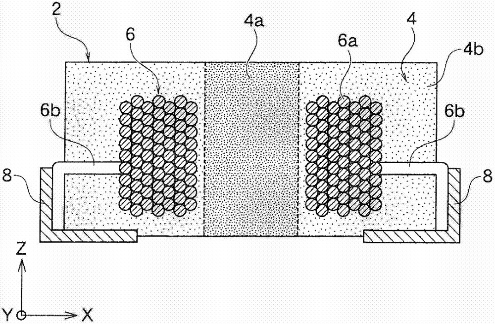
[0068] Such as figure 1 and figure 2 As shown, the inductance element 2 in one embodiment of the present invention has a core 4 which is a compression molded body, and a winding part 6 in which a conductor 6 a is wound in a coil shape inside the core 4 . The conductor 6a is composed of, for example, a wire and an insulating coating corresponding to the outer periphery of the wire that needs to be covered.
[0069] The wire is made of, for example, Cu, Al, Fe, Ag, Au, phosphor bronze, or the like. The insulating cover layer is made of, for example, polyurethane, polyamideimide, polyimide, polyester, polyesterimide, polyester nylon, or the like. The cross-sectional shape of the conductor 6a is not particularly limited, and examples thereof include a circular shape, a rectangular shape, and the like.
[0070] The core 4 is formed by compression-molding pellets containing magnetic powder and a binder. The magnetic powder is not particularly limited, and ferrite such as Mn-Zn,...
no. 2 Embodiment approach
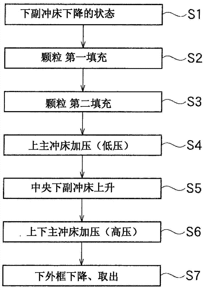
[0097] In the above embodiment, in image 3 The particles in the first filling performed in step S2 and the particles in the second filling performed in step S3 are the same particles, but different particles are used in this embodiment. Other than that, this embodiment is the same as the above-mentioned first embodiment, and can achieve the same effect. Hereinafter, different parts will be described in detail, and descriptions of common parts will be partially omitted.
[0098] In this embodiment, if Figure 6A As shown, the first particles 4Aa filled before disposing the winding part 6 as an insertion member in the cavity 20 and the first particles 4Aa filled in the cavity 20 after disposing the winding part 6 inside the cavity 20 2 particles are different.
[0099] Thereafter, if Figure 6B As shown, low-pressure pressurization is carried out by the upper main punch press 14 . The pressing force between the upper main punch 14 and the lower main punch 12 is the same as...
Embodiment 1
[0111] First, the preparation should be filled to Figure 4A Particles within cavity 20 of mold 10 are shown. A silane coupling agent dissolved in water was added to 100 g of Fe-Si-Cr alloy (average particle size: 0.5 to 10 μm) as magnetic powder, and heated at 110°C for 30 minutes to form an insulating coating on the surface of the magnetic powder. To the above-mentioned magnetic powder, 3% by weight of epoxy resin diluted in acetone was added and stirred with respect to the weight of the magnetic powder, and then passed through a mesh with a pore size of 250 μm and dried at room temperature for 24 hours, thereby Obtain magnetic powder particles.
[0112] Such as Figure 4B As shown, in the mold 10 , the magnetic powder including the binder is put into 1 / 3 of the depth of the mold (the entire depth of the cavity to the upper surface of the lower main punch 12 ). At this time, the lower sub punch 18 in the center of the lower part of the die is lowered by about 3 mm relativ...
PUM
 Abstract
Description
Claims
Application Information
 - R&D
- Intellectual Property
- Life Sciences
- Materials
- Tech Scout
- Unparalleled Data Quality
- Higher Quality Content
- 60% Fewer Hallucinations
Browse by: Latest US Patents, China's latest patents, Technical Efficacy Thesaurus, Application Domain, Technology Topic, Popular Technical Reports.
© 2025 PatSnap. All rights reserved.Legal|Privacy policy|Modern Slavery Act Transparency Statement|Sitemap|About US| Contact US: help@patsnap.com