
Two-mobile-terminal mutual testing method and system

A mobile terminal and mutual testing technology, which is applied in the transmission system, telephone communication, transmission monitoring, etc., can solve the problem of low efficiency of mobile terminals, and achieve the effect of simple and convenient testing, simple operation, and reduced testing time

Active Publication Date: 2014-04-09
PHICOMM (SHANGHAI) CO LTD
View PDF5 Cites 15 Cited by
  • Summary
  • Abstract
  • Description
  • Claims
  • Application Information

AI Technical Summary

Problems solved by technology

[0006] In view of the shortcomings of the prior art described above, the purpose of the present invention is to provide a method and system based on mutual testing of two mobile terminals, which is used to solve the problem of low efficiency in testing mobile terminals in the prior art

Method used


Image

  • Two-mobile-terminal mutual testing method and system
  • Two-mobile-terminal mutual testing method and system
  • Two-mobile-terminal mutual testing method and system

Examples


Embodiment 1

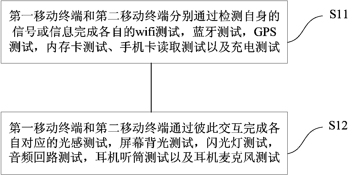
[0033] This embodiment provides a method based on mutual testing of two mobile terminals, which is applied to the first mobile terminal and the second mobile terminal to be tested. Please refer to figure 1 , which is a schematic flowchart of a method based on mutual testing of two mobile terminals according to the present invention. like figure 1 As shown, a method of the present invention based on mutual testing of two mobile terminals includes the following steps.

[0034] Step S11 , the first mobile terminal and the second mobile terminal respectively complete their own wifi test, bluetooth test, GPS test, memory card test, mobile phone card reading test and charging test by detecting their own signals or information.

[0035] Step S12 , the first mobile terminal and the second mobile terminal interact with each other to complete their corresponding light perception test, screen backlight test, flashlight test, audio loop test, earphone test and earphone microphone test. ...

Embodiment 2

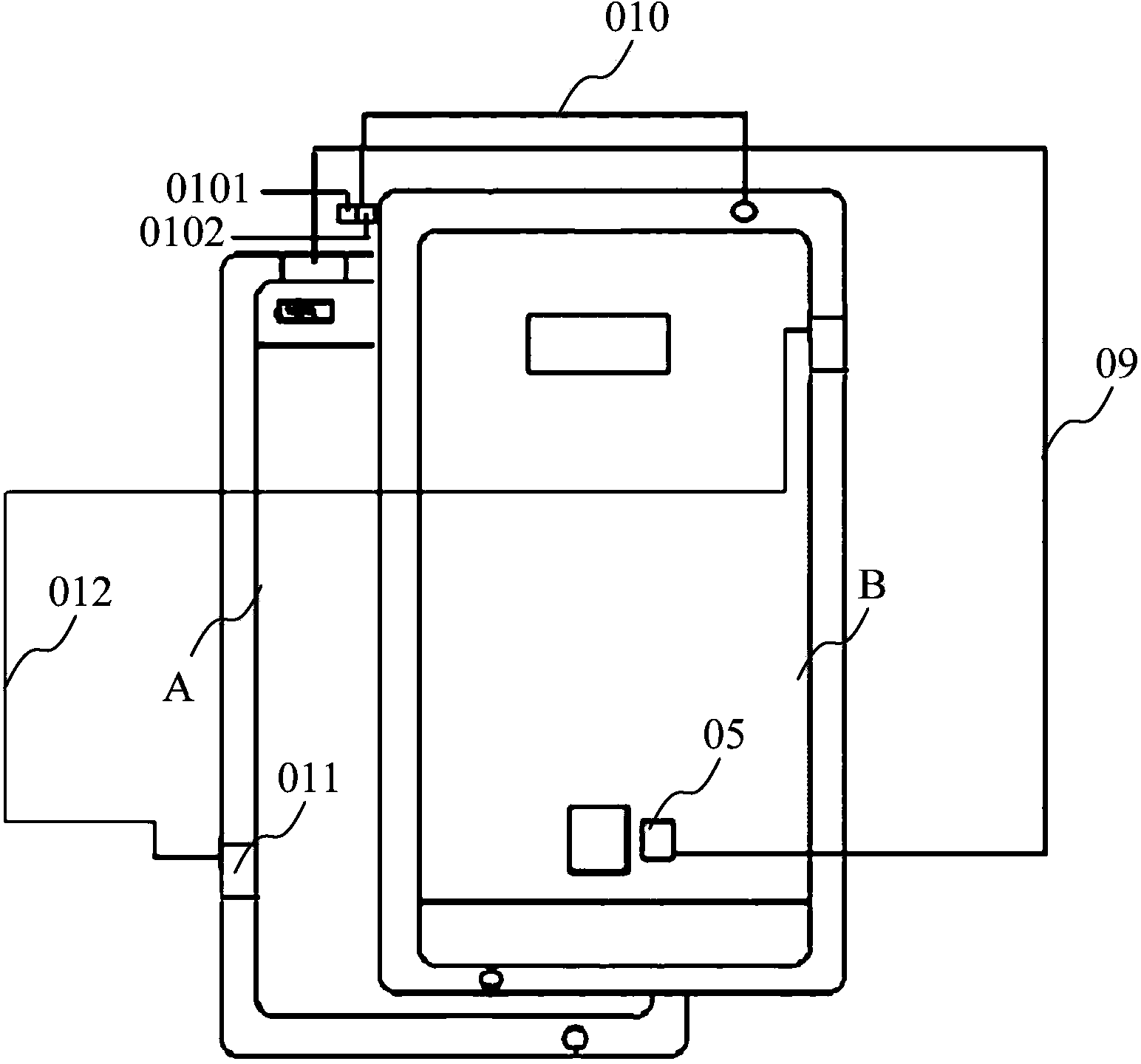
[0074] To implement the above method, such as Figure 7 As shown, this embodiment provides a system based on mutual testing of two mobile terminals. The system 1 based on mutual testing of two mobile terminals includes: a first mobile terminal A to be tested and a second mobile terminal B, an independent test Module 11 and interactive testing module 12.

[0075] In this embodiment, the first mobile terminal A and the second mobile terminal B may be smart phones, PADs and the like.

[0076] The independent test modules 11 are respectively installed in the first mobile terminal A and the second mobile terminal B, and are used for the first mobile terminal A and the second mobile terminal B to complete respective wifi tests and bluetooth tests by detecting their own signals or information. , GPS test, memory card test, mobile phone card reading test and charging test.

[0077] Specifically, the independent test module 11 completes respective wifi tests by detecting the quantity...


PUM


Abstract

The invention provides a two-mobile-terminal mutual testing method and system. The testing method and system are applied to a first mobile terminal to be tested and a second mobile terminal to be tested. The method includes the steps that the first mobile terminal and the second mobile terminal complete wifi testing, Blueprint testing, GPS testing, memory card testing, mobile phone card reading testing and charging testing respectively by detecting respective signals or information; the first mobile terminal and the second mobile terminal complete corresponding light sensing testing, screen backlight testing, flashlight testing, voice frequency circuit testing, earphone receiver testing and earphone microphone testing through mutual interaction; testing reports containing all testing results of the first mobile terminal and the second mobile terminal are generated and are displayed respectively on the display screen of the first mobile terminal and the display screen of the second mobile terminal. Through the two-mobile-terminal mutual testing method and system, the effect of simultaneously testing the two mobile terminals to be tested is achieved, the testing time is effectively reduced and the testing efficiency is improved.

Description

technical field [0001] The present invention relates to the technical field of mobile terminals, in particular to the technical field of mobile terminal testing, specifically a method and system based on mutual testing of two mobile terminals. Background technique [0002] At present, the production line adopts manual control function to test and produce mobile phones. Each employee can only test one machine at a time. Each test requires employees to manually judge whether it is a good product or a defective product. For example, wifi testing requires employees to manually turn on the wifi function and wait for the mobile phone to search The nearby wifi is set up. When the employee sees 5 wifi signals displayed on the display, click the test to pass and enter the next test. It takes 12 points to pass or fail the test to complete the test of a machine, and the operation steps are cumbersome. [0003] During the mass production of mobile phones, due to the operating status of...

Claims


Application Information

Patent Timeline
Patent Type & Authority Applications(China)
IPC IPC(8): H04M1/725H04M1/24H04B17/00
Inventor 孙磊
Owner PHICOMM (SHANGHAI) CO LTD
Learn More