Forming hydraulic machine for hot-press seal head

A hydraulic press and head technology, applied in the field of hydraulic press equipment, can solve the problems of reducing the strength of the column 3 and the tensile slider 4, the height direction of the column 3 becoming longer, and the opening of the stretching slider 4 being large, etc. The effect of weight and easy operation

Active Publication Date: 2014-04-16
HEFEI METALFORMING MACHINE TOOL
View PDF9 Cites 7 Cited by
  • Summary
  • Abstract
  • Description
  • Claims
  • Application Information

AI Technical Summary

Problems solved by technology

[0004] There are following deficiencies in the hot-pressed head forming hydraulic machine of the existing structure: 1. Since the blank holder slider 5 and the stretch slider 4 are all connected together by the column 3, the stretch slider 4 is at the top and the blank holder slider 5 is at the top. Below, the stretching slider 4 needs to pass through the blank holder slider 5 to connect with the pressure cylinder 10. The structure is complicated and consumes a lot of materials. The opening of the stretching slider 4 is large, and the height direction of the column 3 becomes longer, so the column 3 and the column 3 are reduced. The strength of the stretching slider 4, and because the blank holder slider 5 and the stretch slider 4 are up and down structures, their guiding performance is poor; two, the stretch slider 4 and the blank holder slider 5 are separated when forming the workpiece For working, the stretching force and the blank holder force are both fixed values, which cannot be converted or combined; 3. Even if the blank holder slider 5 and the stretch slider 4 are locked together to become a single action, The structure is more complicated and the operation is also very inconvenient

Method used


Image

  • Forming hydraulic machine for hot-press seal head
  • Forming hydraulic machine for hot-press seal head
  • Forming hydraulic machine for hot-press seal head

Examples


Embodiment Construction

[0018] The embodiments of the present invention are described in detail below. This embodiment is implemented on the premise of the technical solution of the present invention, and detailed implementation methods and specific operating procedures are provided, but the protection scope of the present invention is not limited to the following implementation example.

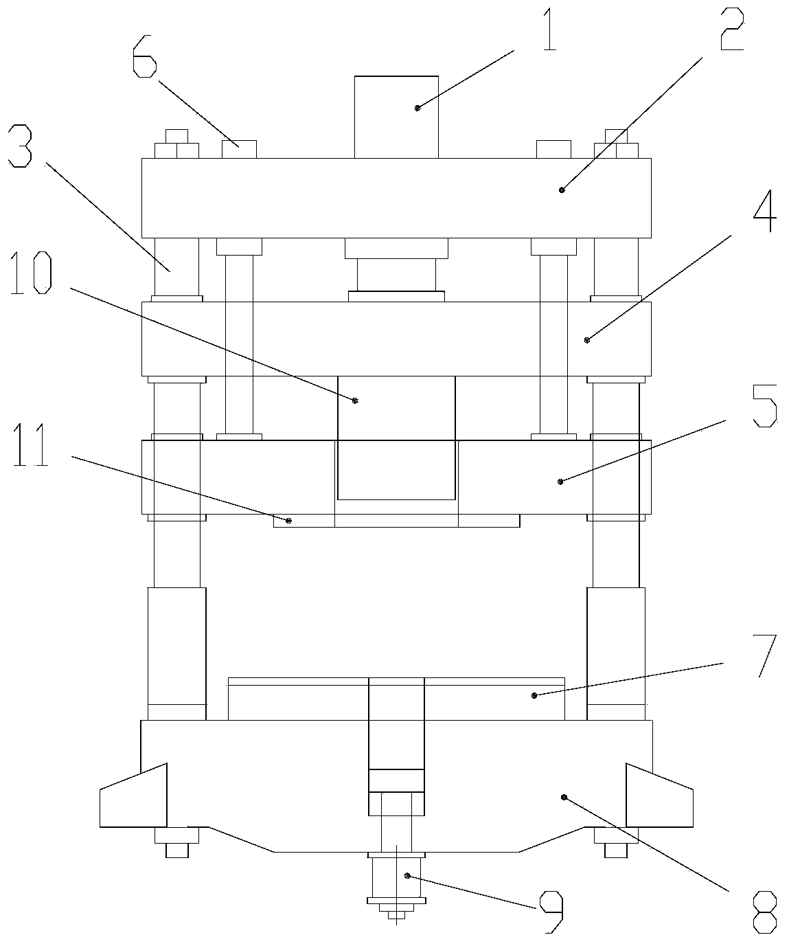
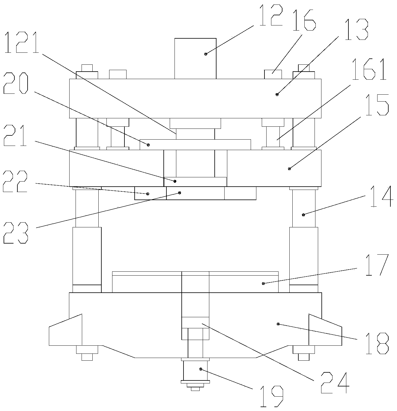
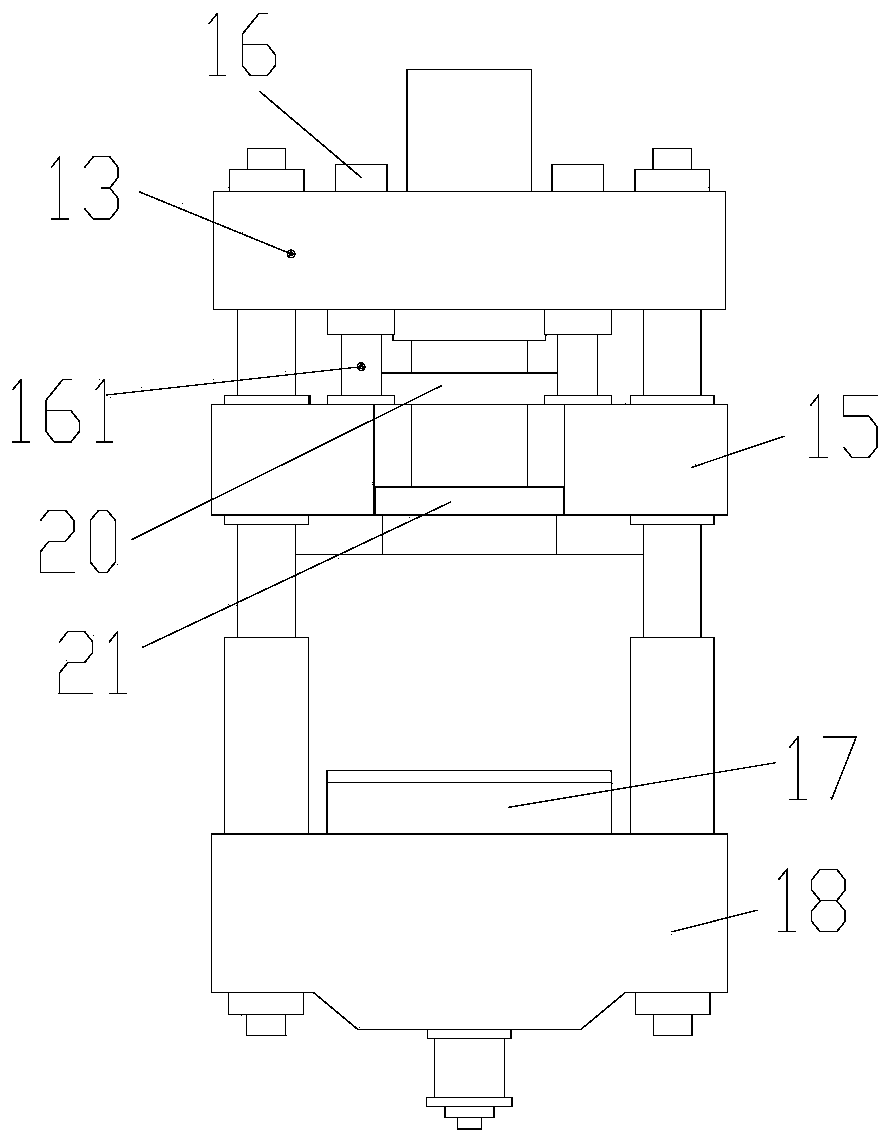
[0019] see figure 2 , image 3 , a kind of hot-pressed head forming hydraulic machine provided by the present invention comprises a frame, four columns 14 arranged on the frame, an upper beam 13 and a lower beam 18 fixedly arranged on the column 14, and the lower beam 18 is provided with Mobile workbench 17 is used to install lower mold on the mobile workbench 17. The lower end of the lower beam 18 is provided with an ejection cylinder 19, and the ejection cylinder 19 extends upwards with a push rod 24. Between the upper crossbeam 3 and the lower crossbeam 18, there is a blanking slider 15 that can move up and ...


PUM


Abstract

The invention discloses a forming hydraulic machine for a hot-press seal head. The forming hydraulic machine comprises a machine frame, four vertical columns arranged on the machine frame, an upper beam and a lower beam, wherein the upper beam and the lower beam are fixedly arranged on the four vertical columns. An edge pressing and sliding block capable of vertically moving along the vertical columns is arranged between the upper beam and the lower beam, a vertically through guide groove is formed in the middle of the edge pressing and sliding block, a tension hydraulic cylinder is arranged in the middle of the upper beam in a through mode, the lower end of a tension piston rod of the tension hydraulic cylinder is connected with a tension sliding block, the tension sliding block can vertically move in the guide groove of the edge pressing and sliding block, the lower end of the tension sliding block is fixedly provided with a bearing tube, and the lower end of the bearing tube is provided with an upper die. The upper beam is further provided with at least two edge pressing hydraulic cylinders, and the lower end of an edge pressing piston rod of each edge pressing hydraulic cylinder is connected with the edge pressing and sliding block. The forming hydraulic machine for the hot-press seal head has the following advantages of being good in guide performance, capable of achieving double movements into a single movement, simple in structure, safe, reliable and convenient to operate.

Description

technical field [0001] The invention relates to the field of hydraulic press equipment, in particular to a hydraulic press for forming hot-pressed heads. Background technique [0002] The hot-pressed head forming hydraulic machine is specially used for the pressing and forming process of the hot-pressed head, and is widely used in the hot-pressed head forming of various specifications and different materials. [0003] see figure 1 , In the prior art, the hot-press head forming hydraulic machine mainly includes an upper beam 2, a lower beam 8, a column 3, a stretching slider 4, a blank holder slider 5, and a workbench 7. The fuselage of the three-beam four-column hydraulic press connects the above structures through the column 3, and the stretching hydraulic cylinder 1 for driving the stretching slider 4 and the blanking hydraulic cylinder 6 for driving the blanking slider 5 are all arranged on the On the upper beam 2 , a pressure bearing cylinder 10 is arranged on the stre...

Claims


Application Information

Patent Timeline
Patent Type & Authority Applications(China)
IPC IPC(8): B21D22/22B21D24/08B21D51/44B30B15/00B30B15/04
Inventor 侯一江
Owner HEFEI METALFORMING MACHINE TOOL
Why Eureka
Try Eureka