Hard alloy and method for producing hard alloy layer on surface of workpiece

A technology of hard alloy and workpiece surface, which is applied in the direction of manufacturing tools, metal processing equipment, gas flame welding equipment, etc., can solve the problem of high equipment requirements, achieve the effect of simple equipment, convenient operation, and saving manufacturing costs

Inactive Publication Date: 2014-04-16
烟台开发区蓝鲸金属修复有限公司
View PDF6 Cites 10 Cited by
  • Summary
  • Abstract
  • Description
  • Claims
  • Application Information

AI Technical Summary

Problems solved by technology

Commonly used wear-resistant parts adopt conventional heat treatment, such as carburizing, nitriding or carbonitriding, surface quenching or casting and other treatment processes to add to the surface of the workpiece. These treatment methods require relatively professional or large-scale equipment. Realization, equipment requirements are high, and conventional heat treatment methods will have different restrictions due to different base materials or workpiece sizes

Method used


Image

  • Hard alloy and method for producing hard alloy layer on surface of workpiece
  • Hard alloy and method for producing hard alloy layer on surface of workpiece

Examples


Embodiment 1

[0026] The mass ratio of each component of the cemented carbide in this embodiment is: WC50%, Co30%, Mo20%, wherein 75-150 μm WC accounts for 10% of the whole WC powder.

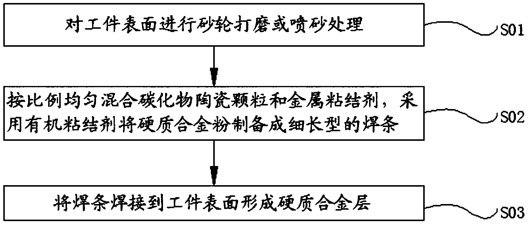
[0027] Manufacture the hard alloy layer on the surface of the workpiece according to the following process:

[0028] Step 1, grinding or sandblasting the surface of the workpiece;

[0029] Step 2, uniformly mixing the carbide ceramic particles and the metal binder according to the above ratio, and preparing the cemented carbide powder into a slender electrode by using an organic binder;

[0030] Step 3, welding the welding rod to the surface of the workpiece by means of flame welding to form a cemented carbide layer.

Embodiment 2

[0032] The mass ratio of each component of the cemented carbide in this embodiment is: WC 80%, Co 20%, wherein 75-150 μm WC accounts for 90% of the whole WC powder.

[0033] Manufacture the hard alloy layer on the surface of the workpiece according to the following process:

[0034] Step 1, grinding or sandblasting the surface of the workpiece;

[0035] Step 2, uniformly mixing the carbide ceramic particles and the metal binder according to the above ratio, and preparing the cemented carbide powder into a slender electrode by using an organic binder;

[0036] Step 3, welding the welding rod to the surface of the workpiece by means of flame welding to form a cemented carbide layer.

Embodiment 3

[0038] The mass ratio of each component of the cemented carbide in this embodiment is: WC65%, Co25%, Mo10%, wherein 75-150 μm WC accounts for 50% of the whole WC powder.

[0039] Manufacture the hard alloy layer on the surface of the workpiece according to the following process:

[0040] Step 1, grinding or sandblasting the surface of the workpiece;

[0041] Step 2, uniformly mixing the carbide ceramic particles and the metal binder according to the above ratio, and preparing the cemented carbide powder into a slender electrode by using an organic binder;

[0042] Step 3, welding the welding rod to the surface of the workpiece by means of flame welding to form a cemented carbide layer.


PUM


Abstract

The invention relates to a hard alloy and a method for producing a hard alloy layer on surface of a workpiece. The hard alloy is formed by taking carbide ceramic particles as a matrix and adding a metal adhesive for organically mixing, wherein the carbide ceramic particles refer to a mixture of one or several in WC, TiC, B4C and SiC; the metal adhesive is a mixture of one or several in Co, Ni, Mo, Fe-based alloy powder and Ti; the carbide ceramic particles account for 30-95 percent; the metal adhesive accounts for 5-70 percent. The method for producing the hard alloy layer on the surface of the workpiece comprises the following steps: 1, performing grinding wheel polishing or sand blasting treatment on the surface of the workpiece; 2, preparing the carbide ceramic particles and the metal adhesive which are uniformly mixed into a welding rod; and 3, welding the welding rod on the surface of the workpiece. According to an alloy layer welded on an outer surface of the workpiece, metallurgical bonding between a welding material and a workpiece matrix is ensured, the bonding strength is guaranteed, and the service life of the welded workpiece is increased by several times over.

Description

technical field [0001] The invention relates to a method for manufacturing cemented carbide and a cemented carbide layer on the surface of a workpiece. Background technique [0002] At present, in iron and steel metallurgy, cement, mining machinery, oil drilling and other industries, due to the large friction between some workpieces during use, some machinery needs to be immersed in corrosive liquid, so the surface of the workpiece is in the process of use. Long-term wear and corrosion will seriously affect the performance and service life of the machine. Therefore, in the process of use, there will be greater friction with each other and the surface of the workpiece that needs to be immersed in the corrosive solution will be added with an alloy layer to strengthen the surface strength of the workpiece, thereby reducing the consumption of the workpiece. Commonly used wear-resistant parts adopt conventional heat treatment, such as carburizing, nitriding or carbonitriding, su...

Claims


Application Information

Patent Timeline
Patent Type & Authority Applications(China)
IPC IPC(8): C22C29/06C22C32/00C22C29/08C22C29/10B23K5/00B23K10/02
Inventor 孙京钢陈佃双
Owner 烟台开发区蓝鲸金属修复有限公司
Why Eureka
Try Eureka