Eureka AIR delivers breakthrough ideas for toughest innovation challenges, trusted by R&D personnel around the world.

Sealed high-temperature electrochemical measuring device

A technology of measuring devices and sealing devices, applied in the direction of material electrochemical variables, etc., can solve the problems of affecting the temperature measurement in the constant temperature area, affecting the accuracy of electrochemical measurement, and fast aging

Active Publication Date: 2014-04-16
CHINA INSTITUTE OF ATOMIC ENERGY
View PDF3 Cites 14 Cited by
  • Summary
  • Abstract
  • Description
  • Claims
  • Application Information

AI Technical Summary

Problems solved by technology

Because this kind of research device is not sealed, the residual water and oxygen content in the device are generally still higher than hundreds of ppm (ppm is one millionth), which affects the accuracy of electrochemical measurement; the argon flow will also take away the device A large amount of heat inside affects the temperature measurement in the constant temperature area; the rubber sealing ring is used, which ages faster at high temperatures above 250°C and needs to be replaced frequently
In addition, in terms of the heating method of molten salt electrochemical research devices, induction heating or resistance wire heating is generally used at home and abroad. Both heating methods will generate induced currents, which will affect the electrochemical signal measurement of the electrode reaction.
[0005] At present, there is no sealed high-temperature electrochemical measuring device for the electrochemical measurement of uranium, plutonium and fragment elements in the high-temperature molten salt system for nuclear fuel reprocessing research at home and abroad.

Method used


Image

  • Sealed high-temperature electrochemical measuring device

Examples


Embodiment Construction

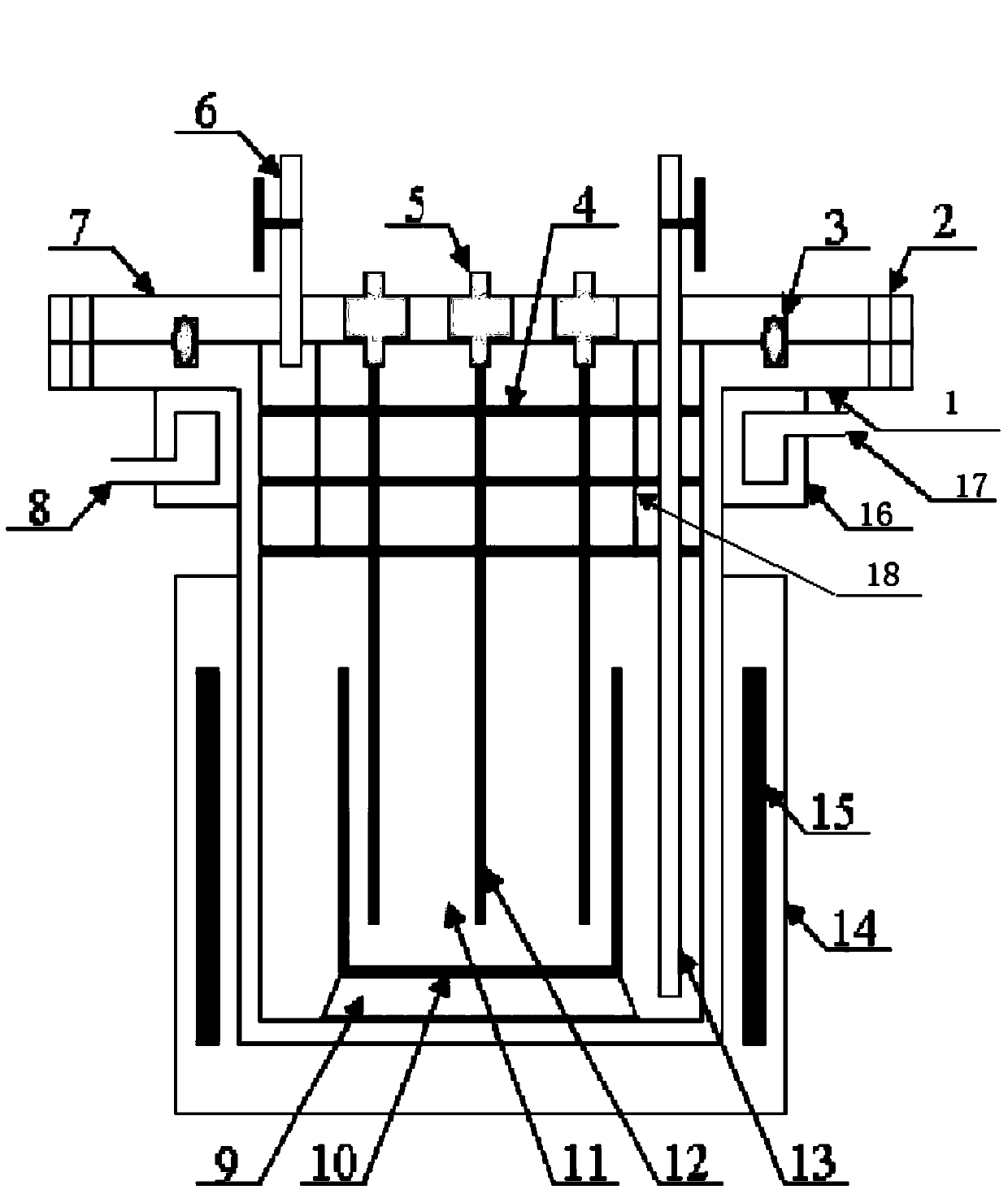
[0024] The following will clearly and completely describe the technical solutions in the embodiments of the present invention with reference to the accompanying drawings in the embodiments of the present invention. Obviously, the described embodiments are only some, not all, embodiments of the present invention. Based on the embodiments of the present invention, all other embodiments obtained by persons of ordinary skill in the art without making creative efforts belong to the protection scope of the present invention.

[0025] like figure 1 As shown, it is a schematic structural diagram of a sealed high-temperature electrochemical measurement device according to an embodiment of the present invention. The sealed high-temperature electrochemical measurement device includes:

[0026] The sealing device includes an upper flange 7 and a lower flange 1, wherein both the upper flange 7 and the lower flange 1 are superalloys (the superalloy is a nickel-based superalloy), and the low...


PUM


Abstract

The embodiment of the invention provides a sealed high-temperature electrochemical measuring device which comprises a sealing device, a heating device, an electrode body and a gas inlet and outlet, wherein the sealing device comprises an upper flange and a lower flange; both the upper flange and the lower flange are made of high-temperature alloys; the lower flange is tank-shaped; the upper flange is cover-shaped and is positioned at the opening of the lower flange; the upper flange and the lower flange are sealed through a metal graphite sealing ring and a bolt; the heating device is positioned on the outer side of the lower part of the lower flange and wraps the lower part of the lower flange; the electrode body and the upper flange are integrally designed; the electrode body extends into molten salt contained in a crucible in the tank body of the lower flange, and is used for outputting electrochemical signals from the sealed high-temperature electrochemical measuring device; the gas inlet and outlets are integrated on the upper flange in a sealed manner and are used for feeding and discharging inert gases. According to the embodiment of the invention, the device has the functions of high-temperature heating, high-temperature sealing, inert atmosphere protection, electrochemical signal output under sealing condition, and the like, and the accuracy in fused salt electrochemical measurement on uranium, plutonium and bothridium elements is improved.

Description

technical field [0001] The invention relates to the technical field of nuclear fuel reprocessing, in particular to a sealed high-temperature electrochemical measuring device. Background technique [0002] The dry reprocessing process based on molten salt electrochemical separation technology is currently the most in-depth research in the world, and is considered to be the most promising dry reprocessing process for fast reactor spent fuel. The key to the molten salt electrolytic dry reprocessing process is the precise control of the separation potential of uranium, plutonium and splinter elements, which in turn depends on the accurate measurement of the potential of uranium, plutonium and splinter elements. [0003] The molten salt electrolytic dry post-treatment process involves high-temperature operation of highly chemically active actinide and lanthanide metals and highly water-absorbing chloride molten salts. At high temperature, uranium and plutonium metals are very ea...

Claims


Application Information

Patent Timeline
Patent Type & Authority Applications(China)
IPC IPC(8): G01N27/26
Inventor 林如山何辉唐洪彬叶国安
Owner CHINA INSTITUTE OF ATOMIC ENERGY
Why Eureka
Eureka Blog
Learn More