Antenna tuner impedance detection method based on phase detection

A technology of impedance detection and phase detection, which is applied in the direction of measuring resistance/reactance/impedance, instruments, measuring devices, etc., can solve the problems of reducing system emission efficiency, potential safety hazards, heating of final power amplifier, etc., to ensure tuning speed and resources The effect of less consumption and precise measurement

Inactive Publication Date: 2014-04-16
TOEC TECH
View PDF5 Cites 9 Cited by
  • Summary
  • Abstract
  • Description
  • Claims
  • Application Information

AI Technical Summary

Problems solved by technology

The impedance mismatch between the antenna and the feeder will cause part of the output power of the final stage of the transmitter sent by the feeder to be reflected back by the antenna, which will affect the normal working state of the final power amplifier, and may cause the final power amplifier to heat up and even burn out, reducing the power consumption of the final power amplifier. The emission efficiency of the system, and there are safety hazards at the same time

Method used


Image

  • Antenna tuner impedance detection method based on phase detection
  • Antenna tuner impedance detection method based on phase detection
  • Antenna tuner impedance detection method based on phase detection

Examples


Embodiment Construction

[0022] In order to understand the present invention more clearly, the present invention is described in detail with reference to the accompanying drawings and embodiments:

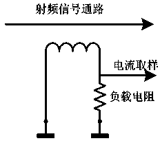
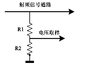
[0023] like Figure 1 to Figure 7 As shown, the current sampling circuit adopts the form of inductive coil coupling to couple a certain current signal from the radio frequency link. Voltage sampling is obtained from the RF link in the form of a resistive voltage divider.

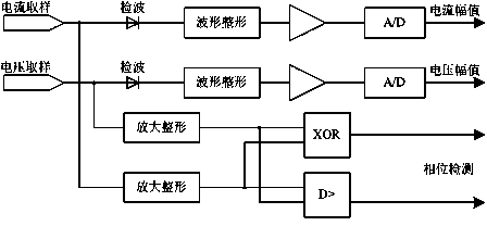
[0024] The current sampling and the current sampling signal pass through the diode detection circuit, and then the amplifier is used for waveform shaping and amplification, and the current amplitude and voltage amplitude are obtained through A / D sampling. The shunt signal of the current sampling signal and the voltage sampling signal is shaped by the comparator, and the waveform is changed from a sine wave to a square wave, and then the square wave signal is amplified to obtain a standard square wave signal. The voltage square wav...


PUM


Abstract

The invention relates to an antenna tuner impedance detection method based on phase detection. The method includes the following steps that firstly, the inductance coil coupling mode is adopted in a current sampling circuit, and a voltage sampling signal is acquired from a radio frequency link in a resistance voltage dividing mode; secondly, a circuit sampling signal and the voltage sampling signal are subjected to detection, amplifying and A / D sampling to acquire a current amplitude value and a voltage amplitude value; thirdly, shunt signals of the current sampling signal and voltage sampling signal are subjected to wave shaping through a comparator, a sine wave becomes a square wave, then the square wave is amplified, and a standard square-wave signal is acquired; fourthly, the phase of an impedor and the relation between the capacitive reactance and the inductive reactance of the impedor are judged through the voltage and current shaping square wave signals and a voltage and current square wave xor output signal. The method has the advantages that the input impedance of an antenna can be precisely measured, resource consumption is small, circuits are simple, the measurement speed is high and the tuning speed of an antenna tuner can be guaranteed.

Description

technical field [0001] The invention relates to equipment for wireless communication and radio wave propagation, in particular to a method for impedance detection of an antenna tuner based on phase detection. Background technique [0002] At present, with the development of communication technology, there are more and more applications of long-distance communication. Long-distance communication establishes link communication by transmitting high-power signals through antennas. The input impedance of the antenna radiating element is a function of the operating frequency, antenna type, antenna size and the surrounding environment. Its input impedance will change greatly with the changes of the above factors, while the output impedance of the transmitter power stage is relatively unchanged . If the transmitter is directly connected to the antenna, when the operating frequency of the transmitter and other factors change, the impedance between the transmitter and the ...

Claims


Application Information

Patent Timeline
Patent Type & Authority Applications(China)
IPC IPC(8): G01R27/08
Inventor 邓力鹏张鹏泉曹晓冬范玉进李柬褚孝鹏李光张波李羚梅
Owner TOEC TECH
Why Eureka
Try Eureka