Method for diagnosing fault of low-voltage frequency converter

A technology of fault diagnosis and frequency converter, applied in the direction of instruments, measuring electrical variables, measuring devices, etc., can solve problems such as lack of practicability

Active Publication Date: 2014-04-16
BEIJING CERISTAR ELECTRIC +1
View PDF6 Cites 16 Cited by
  • Summary
  • Abstract
  • Description
  • Claims
  • Application Information

AI Technical Summary

Problems solved by technology

This method can obtain the specific types of faults and the more accurate location of the generator inverter fault, which has the advantages of saving maintenance costs and providing reference for the early design of wind turbines; however, this method must establish a complex mathematical model to simulate For various faults of the inverter, the fault simulation results are obtained. After the data collection and analysis of the actual operating state of the inverter, and the analogy judgment with the fault simulation results, the self-diagnosis function can be completed. Therefore, it is limited by the mathematical model analysis of the inverter fault state , using complex control theory, self-learning and correcting the model while using it, which lacks practicality and can only be used as an ideal theoretical analysis

Method used


Image

  • Method for diagnosing fault of low-voltage frequency converter
  • Method for diagnosing fault of low-voltage frequency converter
  • Method for diagnosing fault of low-voltage frequency converter

Examples


Embodiment 1

[0088] This embodiment provides a specific low-voltage inverter fault diagnosis process, such as Figure 4 shown, including the following steps:

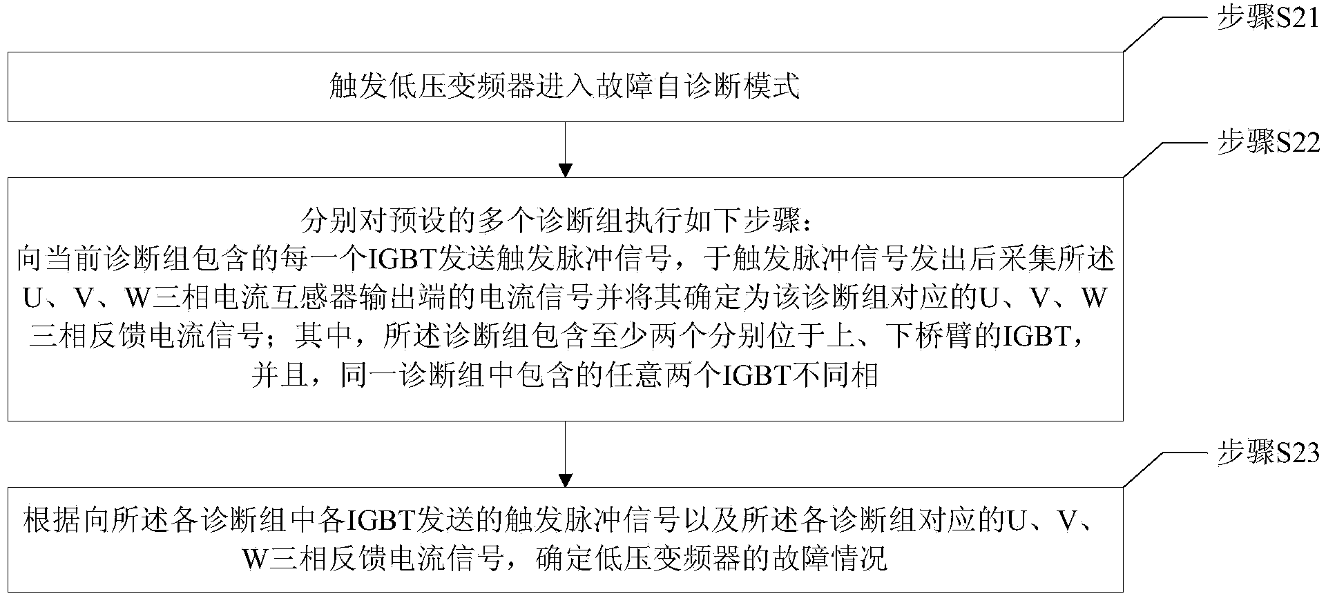
[0089] Step S41, judge whether to enter the fault diagnosis mode according to the preset trigger mechanism, if so, execute step S42, otherwise repeat this step;

[0090] Step S42, sending a trigger pulse signal to all the IGBTs included in the current diagnosis group, and collecting the current signals at the output ends of the U, V, and W three-phase current transformers after the signal is sent;

[0091] Step S43, judging whether all diagnosis groups have been diagnosed, if yes, execute step S44, otherwise execute step S47;

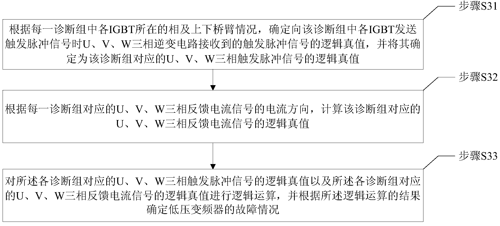
[0092] Step S44, calculating the logical truth value of the U, V, W three-phase trigger pulse signal corresponding to each diagnostic group, and the logical true value of the U, V, W three-phase feedback current signal corresponding to each diagnostic group;

[0093] Step S45, carry out logical operation on...

Embodiment 2

[0097] In this embodiment, a specific logical operation process is used to illustrate the fault diagnosis method of the low-voltage frequency converter of the present invention.

[0098] This embodiment adopts the diagnostic group settings shown in Table 1, and when the diagnostic group includes the U-phase / V-phase / W-phase upper-bridge arm IGBT, the U-phase / V-phase / W-phase trigger pulse signal corresponding to the diagnostic group The logic truth value of t=1, when the diagnosis group contains U phase / V phase / W phase lower bridge arm IGBT, the logic truth value of the U phase / V phase / W phase trigger pulse signal corresponding to the diagnosis group is -t =-1, then the logical truth of the U, V, W three-phase trigger pulse signals corresponding to each diagnostic group is shown in Table 2.

[0099] Table 2

[0100]

[0101] In this embodiment, when the U-phase / V-phase / W-phase feedback current signal corresponding to the diagnosis group is forward current, the logic truth va...

Embodiment 3

[0121] In this embodiment, another specific logical operation process is used to illustrate the fault diagnosis method of the low-voltage frequency converter of the present invention.

[0122] The difference between this embodiment and Embodiment 2 is that the logical truth values ​​of the U, V, and W three-phase feedback current signals corresponding to each diagnosis group in this embodiment are shown in Table 4.

[0123] Table 4

[0124]

[0125]

[0126] Perform logical operations on the logical truth values ​​in Table 2 and Table 4 to obtain the following results:

[0127] A=∑Ua×Iua=∑(1×1+1×1+1×1)=3, where a is the diagnosis group 1, 5 and 6;

[0128] B=∑Vb×Ivb=∑(1×0+1×0+1×0)=0, where b is the first, second and third diagnostic groups;

[0129] C=∑Wc×Iwc=∑(1×1+1×1+1×1)=3, where c is the 3rd, 4th and 5th diagnostic group;

[0130] D=∑Ud×Iud=∑[(-1)×(-1)+(-1)×(-1)+(-1)×(-1)]=3, where d is the 2nd and 3rd , 4 diagnostic groups;

[0131] E=∑Ve×Ive=∑[(-1)×0+(-1)×0+(-...


PUM


Abstract

The invention provides a method for diagnosing a fault of a low-voltage frequency converter. The method is applied to the technical field of automatic control. The method comprises the steps that the low-voltage frequency converter is triggered to enter a fault self-diagnosis mode; according to the steps respectively carried out on a plurality of preset diagnosis sets, trigger pulse signals are sent to IGBTs included in the current diagnosis set, current signals of the current mutual inductor output ends of three phases U, V and W are collected after the trigger pulses signals are sent out and are determined to be the feedback current signals of the three phases U, V and W corresponding to the diagnosis sets; the fault condition of the low-voltage frequency converter is determined according to the trigger pulse signals sent to the IGBTs in the diagnosis sets and the feedback current signals of the three phases U, V and W corresponding to the diagnosis sets. The self diagnosis of a frequency converter core device is achieved by completely adopting a software method, a new hardware structure does not need to be added, and the method has the advantages of being short in diagnosis time, accurate in diagnosis result, low in implementation cost, good in practicality and the like.

Description

technical field [0001] The invention relates to the technical field of automatic control, in particular to a fault diagnosis method for a low-voltage frequency converter. Background technique [0002] Inverter is a high-tech product that integrates power electronics technology, motor drive technology, computer control technology, communication technology and other disciplines. It is the product of the combination of traditional technology and information industry, and is a typical high-end equipment manufacturing category. product. With the development and comprehensive utilization of frequency conversion technology, almost all industries in the national economy are inseparable from frequency converters. Among them, the low-voltage inverter has a sales market size of nearly 12 billion in my country every year. [0003] Due to the relatively complex technology of low-voltage inverters, in order to quickly diagnose the faults of the core components of low-voltage inverters, ...

Claims


Application Information

Patent Timeline
Patent Type & Authority Applications(China)
IPC IPC(8): G01R31/00
Inventor 毛伟闫向峰于洋王俊成曹桂水刘东岳淳
Owner BEIJING CERISTAR ELECTRIC
Why Eureka
Try Eureka