Load test method and test circuit and switching power supply utilizing same

A load detection, switching power supply technology, applied in the semiconductor field, can solve the problems of high power consumption, the effect of switching power supply efficiency, and large voltage difference

Active Publication Date: 2014-04-16
SILERGY SEMICON TECH (HANGZHOU) CO LTD
View PDF6 Cites 44 Cited by
  • Summary
  • Abstract
  • Description
  • Claims
  • Application Information

AI Technical Summary

Problems solved by technology

Generally speaking, the power supply voltage of the synchronous rectification control circuit is about 3.0-3.5V, and when the output voltage is relatively high, such as about 12-19V, the voltage difference in this part will be relatively large, and the power consumption will also be large. It will be relatively large, especially in the light load state, the large power consumption will have a very large impact on the efficiency of the switching power supply

Method used


Image

  • Load test method and test circuit and switching power supply utilizing same
  • Load test method and test circuit and switching power supply utilizing same
  • Load test method and test circuit and switching power supply utilizing same

Examples


Embodiment Construction

[0039] Several preferred embodiments of the present invention will be described in detail below with reference to the accompanying drawings, but the present invention is not limited to these embodiments. The present invention covers any alternatives, modifications, equivalent methods and schemes made on the spirit and scope of the present invention. In order to provide the public with a thorough understanding of the present invention, specific details are set forth in the following preferred embodiments of the present invention, but those skilled in the art can fully understand the present invention without the description of these details.

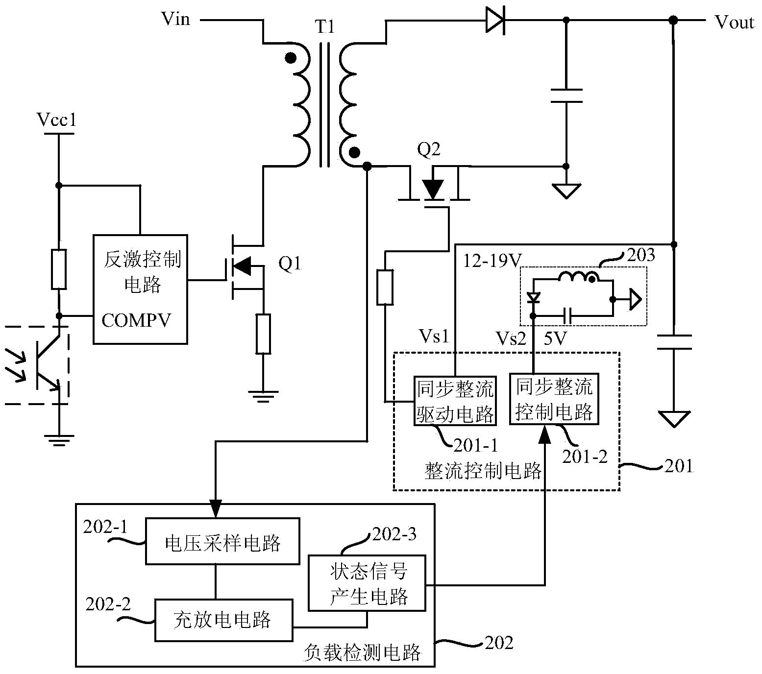
[0040] refer to figure 2 Shown is a circuit block diagram of a flyback switching power supply according to the present invention. In this embodiment, the switch tube Q1 is a power switch tube. The synchronous rectification switch on the side, the rectification control circuit 201 controls the switching state of the switch tube Q2, the r...


PUM


Abstract

The invention discloses a load test method and test circuit and a switching power supply utilizing the same. The voltage change between the first power end and the second power end of a synchronous rectifier switch arranged in the flyback switching power supply is monitored through the load test circuit and accordingly the switch state of a power switch tube arranged in the flyback switching power supply can be determined. When the power switch tube is located in the off state and the off state lasts till a preset time interval, the output end of the flyback switching power supply is located in the no load or light load state. In addition, an auxiliary power supply circuit supplies power for a synchronous rectifier control circuit and accordingly the synchronous rectifier control circuit is not large in power loss when a load is located in the no load or light load state.

Description

technical field [0001] The invention relates to the technical field of semiconductors, in particular to a load detection method and a detection circuit used in switching power supplies. Background technique [0002] The flyback switching power supply can realize the isolation of the primary side and the secondary side, and the output voltage is easy to adjust. There is usually a rectifier on the secondary side of the flyback switching power supply to convert the AC voltage or current of the secondary winding of the transformer into the load required DC voltage or current. In order to reduce the loss of the rectifier, metal-oxide-semiconductor field effect transistors with relatively low on-resistance are usually used as synchronous rectifiers. This synchronous rectification method can improve the conversion efficiency of the power supply. [0003] Such as figure 1 Shown is a circuit block diagram of a flyback switching power supply in the prior art. There is a switch tube ...

Claims


Application Information

Patent Timeline
Patent Type & Authority Applications(China)
IPC IPC(8): G01R31/40G01R31/327G01R31/02H02M3/338
CPCY02B70/1475Y02B70/10
Inventor 张凌栋
Owner SILERGY SEMICON TECH (HANGZHOU) CO LTD
Why Eureka
Try Eureka