Sequential equivalent sampling circuit and method based on delay signals

A technology of equivalent sampling and delaying signals, which is applied in the direction of logic circuit coupling/interface, logic circuit connection/interface layout, electrical components, etc. using field effect transistors, and can solve the problem of not taking into account the minimum delay step of fine delay at the same time and total delay, small delay step size, long total delay, etc., to achieve timing matching, reduce jitter, and expand total delay

Active Publication Date: 2014-04-16
NORTHWEST INST OF NUCLEAR TECH
View PDF4 Cites 19 Cited by
  • Summary
  • Abstract
  • Description
  • Claims
  • Application Information

AI Technical Summary

Problems solved by technology

[0005] The purpose of the present invention is to provide a sequential equivalent sampling circuit and sampling method based on a delay signal with a minimum delay step size of 10 ps and a total delay of 512 ns. The time delay step is small, the delay range of the coarse delay is large, and it has t

Method used


Image

  • Sequential equivalent sampling circuit and method based on delay signals
  • Sequential equivalent sampling circuit and method based on delay signals
  • Sequential equivalent sampling circuit and method based on delay signals

Examples


Embodiment Construction

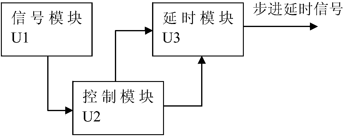
[0043] The invention is used to generate high-precision and large-scale step-delay signals, and the step-delay signal generation circuit and method are widely used in sequential equivalent sampling systems. see figure 1 , the generating circuit includes a signal module U1 for generating signals, a control module U2 for clock debounce and delay adjustment, and a delay module U3.

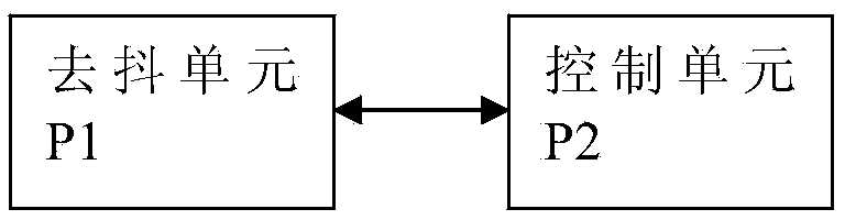
[0044] The control module U2 includes a debounce unit P1 and a control unit P2, see figure 2 . The control module U2 adopts the EP3C16Q240 in Altera's Cyclone III series FPGA. The debounce unit P1 uses the PLL IP core inside the FPGA to accurately divide and multiply the input signal, reduce the output jitter, and improve the signal quality. The main functions of the control unit P2 are: to adjust and control the delay step length of the coarse delay unit P3 and the fine delay unit P5 through the logic function of the FPGA, to realize the output of the delay adjustment signal through the internal l...


PUM


Abstract

The invention provides a sequential equivalent sampling circuit and method based on delay signals. The sampling circuit and method are based on the time broadening principle, and a programmable delay line, a programmable delay chip, a level conversion chip, a highly stable crystal oscillator and an FPGA are used for achieving sampling clock signal delay. The phase-locked loop technology is used for performing phase locking on clock signals output by the highly stable crystal oscillator so as to reduce shaking of a clock; the FPGA is used for controlling the delay step length and the total delay of the programmable delay line and the programmable delay chip; mutual combination of coarse delay of the programmable delay line and fine delay of the programmable delay chip is used, high-precision and large-scale stepping delay is performed on sampling clock signals, the minimum delay step length is 10ps, and the total delay reaches 512ns. The sequential equivalent sampling circuit and method based on the delay signals can be widely applied to a sequential equivalent sampling system.

Description

technical field [0001] The invention relates to a sampling circuit and a sampling method, which is a high-precision and large-range step-delay signal generation circuit and method. The delay technology can be applied to periodic and high-speed measuring instruments, especially the sequential equivalent sampling technology The instrument can improve the delay accuracy, expand the total delay, and improve the measurement accuracy of the instrument. Background technique [0002] The step-delay signal generation circuit and method are widely used in sequential equivalent sampling systems. Current sampling methods are mainly divided into equivalent sampling and real-time sampling, and equivalent sampling is further divided into sequential equivalent sampling and random equivalent sampling. Sequential equivalent sampling has the advantages of simple principle and fast equivalent speed. The sampling points are in time order, which is easy to realize waveform recovery. [0003] At...

Claims


Application Information

Patent Timeline
IPC IPC(8): H03K19/0185H03K17/28
Inventor 李海涛阮林波渠红光田耕田晓霞张雁霞王晶李显宝
Owner NORTHWEST INST OF NUCLEAR TECH
Why Eureka
Try Eureka