Finish machining rotating cutter

A technology of rotating cutting tools and cutting blades, applied in the field of metal cutting tools, can solve the problems of difficult to guarantee cutting edges, reduce processing efficiency, and reduce the quality of the machined surface, so as to improve the cutting performance and machining efficiency, improve the quality of the machined surface, and improve the quality of the machined surface. The effect of surface finish quality

Active Publication Date: 2014-04-23
ZHUZHOU CEMENTED CARBIDE CUTTING TOOLS CO LTD
View PDF6 Cites 9 Cited by
  • Summary
  • Abstract
  • Description
  • Claims
  • Application Information

AI Technical Summary

Problems solved by technology

[0002] During the cutting process of rotary cutting tools, due to the various cutting angles of the rotary cutting tools and the existence of manufacturing and assembly errors, it is difficult to ensure that the cutting edge on the side of the rotary cutting tool is completely on the cylindrical surface. Among them, the machined side is formed by the rotation of the side edge of the tool around the central axis of the rotary cutting tool. Since the cutting edge on the side of the rotary cutting tool is difficult to ensure that it is on the cylindrical surface centered on the central axis, the verticality of the machined surface is not ideal.
At the same time, even if the cutting edge of the cutting blade can be completely controlled on a fixed cylinder, a cutting blade of a structure can only be used on a certain fixed diameter tool. As the diameter of the rotating cutting tool changes, the structural requirements of the cutting blade Corresponding changes occur, resulting in poor versatility of cutting inserts
In order to meet the different diameter process requirements of customers, it is necessary to provide customers with a variety of different cutting inserts, which greatly increases the cost of use, the difficulty of tool site management, and reduces the processing efficiency.
In addition, when the rotary tool is fed in the axial direction, the processing side is formed by the helical rotation of the point at the maximum radial position of the cutting blade, and only a very small part of the cutting blade is in contact with the processing surface. When the rotary tool is suspended When the elongation is large, vibration is very easy to occur during cutting. Cutting vibration can cause rapid wear and tear of the cutting blade, and greatly reduce the quality of the machined surface. In order to ensure the processing accuracy and the service life of the cutting blade, this type of rotary cutting tool can only be used in occasions where the processing efficiency and accuracy are not high

Method used


Image

  • Finish machining rotating cutter
  • Finish machining rotating cutter
  • Finish machining rotating cutter

Examples


Embodiment Construction

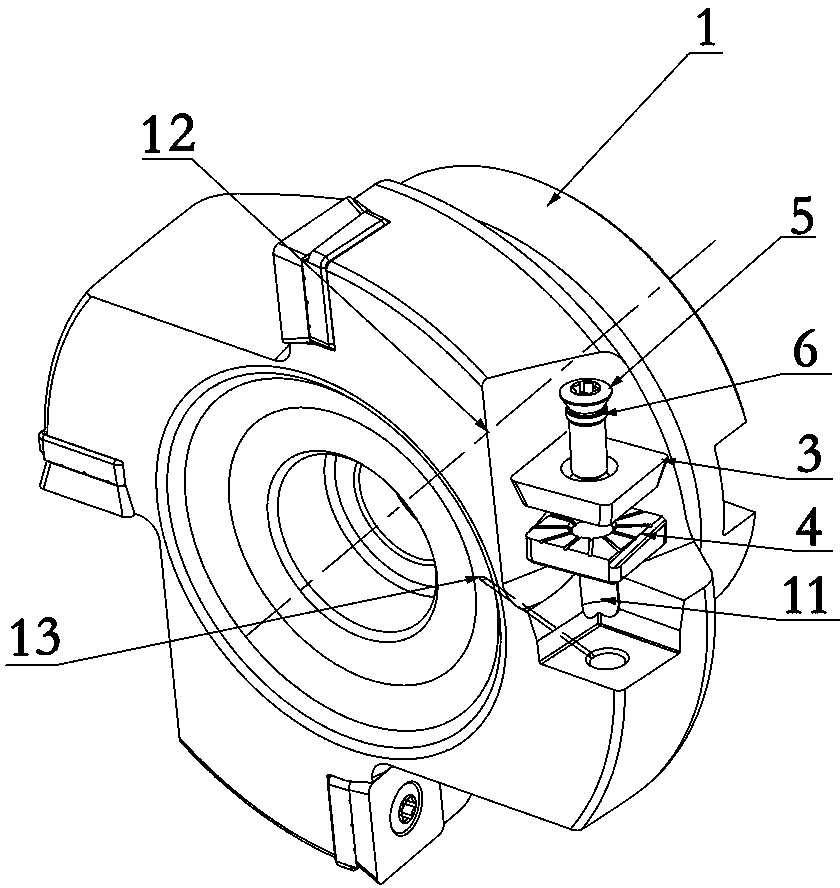
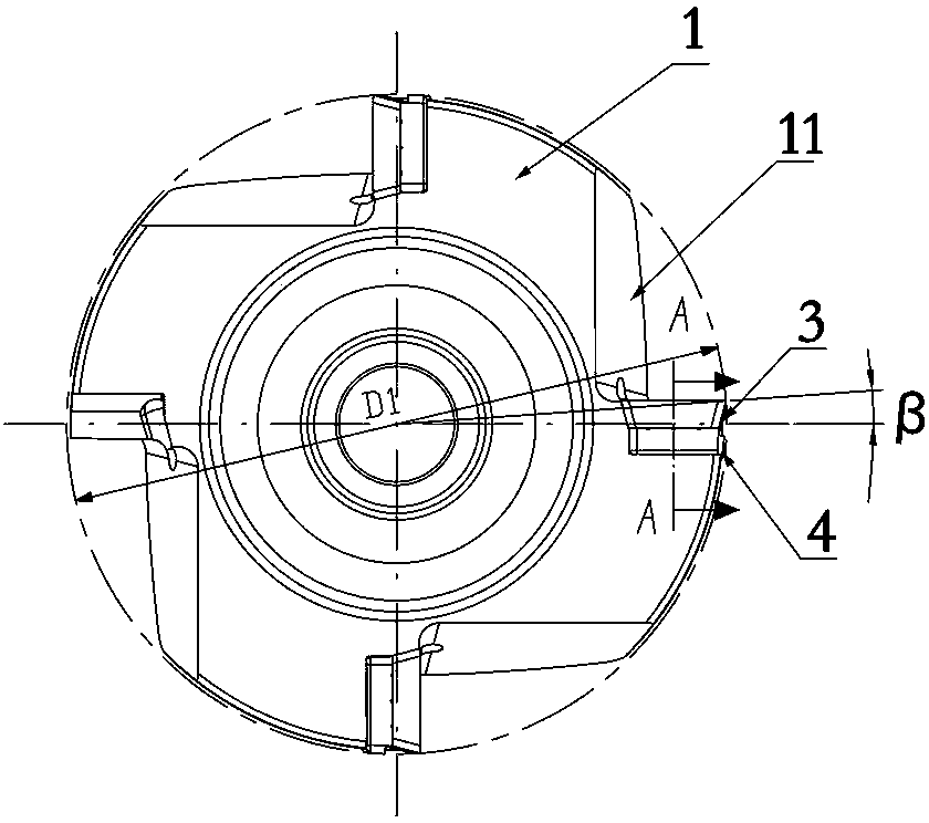
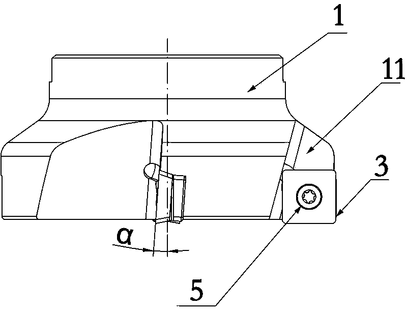
[0027] Figure 1 to Figure 6 The first embodiment of the finishing rotary cutting tool of the present invention is shown. The rotary cutting tool includes a cutter body 1, which is a milling cutter body. A first cutting blade 3 and a second cutting blade 4 are fixed in the groove 11 by a fastener 5, the first cutting blade 3 is pressed on the second cutting blade 4, and the second cutting blade 4 is pressed on the sipe 11, The first cutting insert 3 is provided with a first side cutting edge 31, and the second cutting insert 4 is provided with a second side cutting edge 41 corresponding to the position of the first side cutting edge 31 for guiding anti-vibration and smoothing. The side cutting edge 41 is parallel to the central axis of rotation 12 of the cutter body 1, and adopts the structure of a double-layer cutting blade, so that the second cutting blade 4 of the same type can still be completely attached to the cylindrical processing surface when assembled on a rotating c...


PUM


Abstract

The invention discloses a finish machining rotating cutter. The finish machining rotating cutter comprises a cutter body, wherein the cutter body is provided with at least one group of cutter grooves; each cutter groove is internally provided with a first cutting blade and a second cutting blade which are fixed through a fastener, wherein the first cutting blade is tightly pressed on the second cutting blade, and the second cutting blade is tightly pressed on the cutter grooves; each first cutting blade is provided with a first side surface cutting edge; each second cutting blade is provided with a second side surface cutting edge which corresponds to the position of each first side surface cutting edge and is used for guiding shake resistance and dressing smoothness, and each second cutting blade and a rotating center shaft of the cutter body are parallel. The finish machining rotating cutter disclosed by the invention has the advantages that the structure is simple, the shake resistance and smoothness dressing effects are good, and the surface processing quality is high.

Description

technical field [0001] The present invention relates to a metal cutting tool, in particular to a finishing rotary cutting tool. Background technique [0002] During the cutting process of the rotary cutting tool, due to the various cutting angles of the rotary cutting tool and the existence of manufacturing and assembly errors, it is difficult to ensure that the cutting edge on the side of the rotary cutting tool is completely on the cylindrical surface. Among them, the machined side is formed by the rotation of the side edge of the tool around the central axis of the rotary cutting tool. Since the cutting edge on the side of the rotary cutting tool is difficult to ensure on the cylindrical surface centered on the central axis, the verticality of the machined surface is not ideal. At the same time, even if the cutting edge of the cutting blade can be completely controlled on a fixed cylindrical surface, a cutting blade with a structure can only be used on a certain fixed dia...

Claims


Application Information

Patent Timeline
Patent Type & Authority Applications(China)
IPC IPC(8): B23C5/02B23C5/28B23C5/20
Inventor 江爱胜
Owner ZHUZHOU CEMENTED CARBIDE CUTTING TOOLS CO LTD
Why Eureka
Try Eureka