Intelligent automatic resistance spot-welding device

A resistance spot welding, automatic technology, used in resistance welding equipment, welding equipment, metal processing equipment, etc.

Active Publication Date: 2014-04-23
HUIZHOU DESAY BATTERY
View PDF5 Cites 12 Cited by
  • Summary
  • Abstract
  • Description
  • Claims
  • Application Information

AI Technical Summary

Problems solved by technology

[0003] In order to solve the above technical problems, the present invention provides an intelligent automatic resistance spot we

Method used


Image

  • Intelligent automatic resistance spot-welding device
  • Intelligent automatic resistance spot-welding device
  • Intelligent automatic resistance spot-welding device

Examples


Embodiment Construction

[0014] In order to allow those skilled in the art to better understand the technical solution of the present invention, the present invention will be further elaborated below.

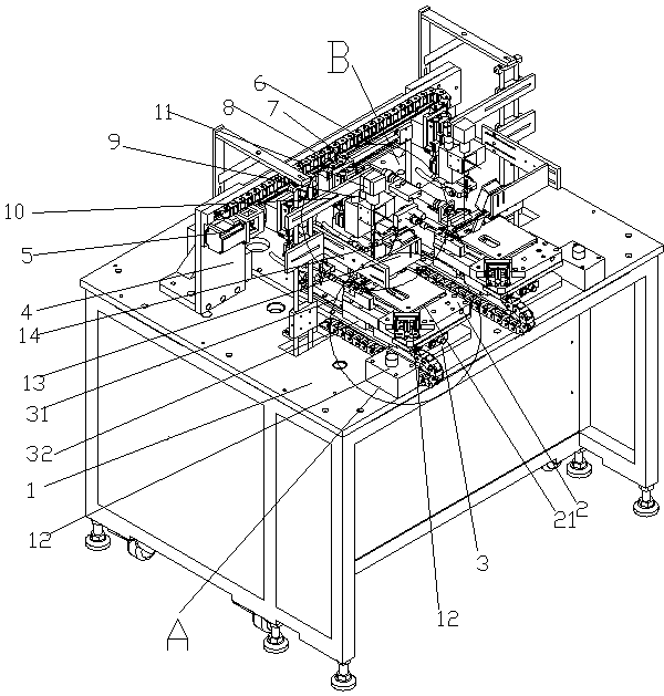
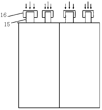
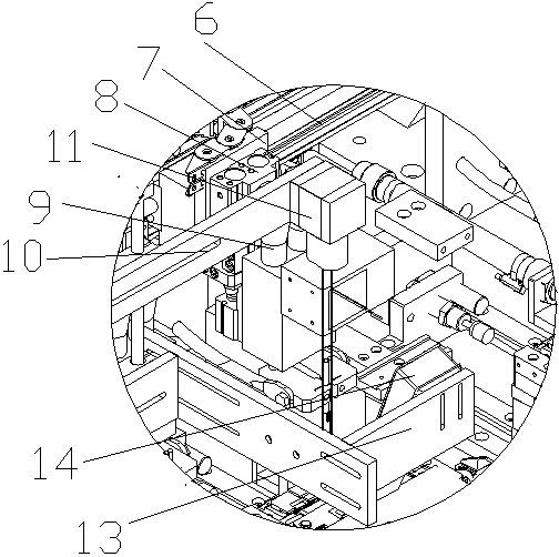
[0015] An intelligent automatic resistance spot welding equipment, comprising a frame 1, on which is provided a cell fixture 2 for placing batteries, the cell fixture 2 is composed of two detachable splints, and the upper end of the cell fixture is provided with The recessed cavity 21 suitable for placing the battery cell is placed on the cavity of the battery holder 2, the height of the cavity is lower than the thickness of the battery cell, and the installed battery cell protrudes out of the cavity of the battery holder. A cell positioning mechanism 12 for positioning the cells is provided on the cell fixture 2, and the cell positioning mechanism 12 is engaged with the cell fixture. The lower end of the cell fixture is provided with a transfer mechanism 3 for transferring the cell fixture. The transf...


PUM


Abstract

The invention discloses an intelligent automatic resistance spot-welding device which comprises a rack. A cell clamp is arranged on the rack, a shifting mechanism is arranged at the lower end of the cell clamp, a switch is arranged on the rack, a fixing support is arranged on the rack, a servo motor is arranged at one end of the fixing support and fixed on a horizontally-arranged guide rail, a fixing plate is further arranged on the guide rail, one side of the fixing plate is connected with the guide rail, an air cylinder is arranged on the other side of the fixing plate, a resistance welding machine is arranged on the other side of the air cylinder, a supporting support is arranged on the rack, and a camera for photographing a cell is fixedly arranged on the supporting support. According to the intelligent automatic resistance spot-welding device, according to the cell actual condition, namely relative position parameters of a tab and a bonding pad, the best welding point position can be judged, and desoldering can be avoided; if the positions of the tab and the bonding pad do not meet the welding condition, badness can be prompted, a cell can be retreated automatically, cell scrapping and resource waste caused by welding position errors are avoided, the economic cost is saved, intelligent automatic control is achieved, and the working efficiency is improved.

Description

technical field [0001] The invention relates to the technical field of electric cores, in particular to an automatic spot welding device capable of automatically identifying the positions of tabs and pads of electric cores, and judging the optimum resistance spot welding position. Background technique [0002] At present, the automatic spot welding equipment used in the industry is based on the set position parameters, and the spot welding head or fixture is driven by a servo motor to perform spot welding at a fixed position. After the servo motor runs to the set position, the spot welding needle goes down, and after touching the pad and tab, discharge welding is performed. However, due to the large tolerance range of the position of the tab of the battery cell, in the case of spot welding at a fixed position, it is easy for the solder spot to be welded outside the tab or on the edge, resulting in the risk of desoldering of the solder joint. Contents of the invention [0...

Claims


Application Information

Patent Timeline
IPC IPC(8): B23K11/11B23K11/36
CPCB23K11/11B23K11/36B23K2101/36
Inventor 李慧颖陈乃勇欧阳一峰
Owner HUIZHOU DESAY BATTERY
Why Eureka
Try Eureka