
Rigid plugging method for mine tailings pond drainage well

A technology for drainage wells and tailings ponds, which is applied in construction, infrastructure engineering, etc., and can solve problems such as plugging failure, construction quality defects, and high thrust of the plugging body, so as to reduce the possibility of leakage, and the implementation is simple and fast. Environmentally friendly effect

Inactive Publication Date: 2014-04-23
CHANGSHA DESIGN & RES INST OF CHEM IND MIN
View PDF4 Cites 12 Cited by
  • Summary
  • Abstract
  • Description
  • Claims
  • Application Information

AI Technical Summary

Problems solved by technology

[0005] At present, the rigid sealing method of the tailings pond drainage well is mainly blocked by rigid materials such as rubble concrete or mortar block stone, which is not ideal in engineering practice. The main reasons for the failure are as follows: 1) The pressure of the overlying tailing The thrust of the plugging body is too large, resulting in the sliding and instability of the plugging body, and the plugging failure; 2) The strength of the plugging body is not enough, resulting in shear failure of the plugging body, and the plugging failure; 3) Defects in construction quality lead to There is a leakage gap with the drainage structure, and the plugging fails

Method used


Image

  • Rigid plugging method for mine tailings pond drainage well
  • Rigid plugging method for mine tailings pond drainage well

Examples


Embodiment Construction

[0024] The present invention will be further described below in conjunction with the accompanying drawings and embodiments.

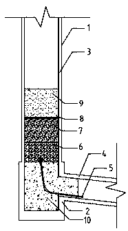
[0025] Referring to the accompanying drawings, the rigid sealing method for drainage wells of mine tailings ponds in this embodiment is to cast in-situ concrete blocking blocks 10 at the junction of drainage well 1 (including well base 2 and derrick 3) and drainage tunnel 4, during the pouring process Pre-buried the drainage steel pipe 5, and set a pebble layer 6 on the concrete block 10, set a sand and gravel layer 7 on the pebble layer 6, set a non-woven geotextile layer Ⅰ8 on the sand and gravel layer 7, and set a non-woven geotextile layer Ⅰ8. A thick tailing sand layer 9 is set, and the inlet end of the drainage steel pipe 5 is wrapped with 3 layers of non-woven geotextiles, placed in the pebble layer 6 above the concrete block in the drainage well section, and the outlet end of the drainage steel pipe 5 is wrapped with 2 layers of non-woven geotext...


PUM


Abstract

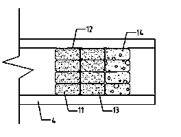
A rigid plugging method for a mine tailings pond drainage well includes: casting in situ to form a concrete plugging block at the junction of the drainage well and a drainage channel, embedding a drainage steel pipe in the casting process, setting a pebble layer on the concrete plugging block, setting a gravel layer on the pebble layer, setting a nonwoven geotextile layer I on the gravel layer, setting a coarse tail sand layer on the nonwoven geotextile layer I, wrapping the entry end of the drainage steel pipe with multiple layers of nonwoven geotextile, placing the entry end in the pebble layer above the concrete plugging block at a drainage well section, and placing the exit end of the steel pipe outside the concrete plugging block at a drainage channel segment; at the exit of the drainage channel, setting a bagged coarse tail sand layer I in the water flow direction, setting a nonwoven geotextile layer II outside the bagged coarse tail sand layer I, setting a bagged coarse tail sand layer II outside the nonwoven geotextile layer II, and setting a bagged gravel layer outside the bagged coarse tail sand layer II. According to the method, by improving stress conditions of a plugging member, plugging failure can be effectively avoided, and construction is simple, fast, economical and environmentally friendly.

Description

technical field [0001] The invention relates to a method for sealing a flood discharge system of a mine tailings reservoir, in particular to a method for rigidly sealing a drainage shaft of a mine tailings reservoir. Background technique [0002] The flood drainage system is one of the key structures of the tailings pond, which plays a very important role in the safety and stability of the tailings pond. The safety accidents of the tailings pond caused by the failure of the flood drainage system account for almost 50% of the total accidents. [0003] Most mine tailings ponds in my country are valley-shaped, and more than 90% of the tailings ponds are piled up by upstream method of damming. The inlet of the flood drainage system of this type of tailings ponds mostly uses drainage wells. The height of the derrick is usually 10-12m, and the current maximum is 50m. [0004] When the height of the tailings accumulation dam exceeds the height of the derrick of the drainage well, t...

Claims


Application Information

Patent Timeline
IPC IPC(8): E02D19/16
Inventor 邓书申陈雯
Owner CHANGSHA DESIGN & RES INST OF CHEM IND MIN
Learn More