Motor decelerator test system

A test system and reducer technology, applied in fluid pressure actuation system testing, mechanical equipment, fluid pressure actuation devices, etc., can solve problems such as high price, low recovery efficiency, unstable test speed, etc., and achieve stable increase performance, and the effect of improving energy recovery efficiency

Inactive Publication Date: 2014-04-23
SUOTE TRANSMISSION EQUIP
View PDF4 Cites 7 Cited by
  • Summary
  • Abstract
  • Description
  • Claims
  • Application Information

AI Technical Summary

Problems solved by technology

Among them, the electrical power recovery method requires the addition of electrical components such as rectification or inverter systems. The technology is complex, expensive, and the recovery efficiency is not high, so it is not the preferred solution of relevant manufacturers; while the hydraulic power recovery method has the advantage of a higher pow

Method used


Image

  • Motor decelerator test system

Examples


Embodiment Construction

[0045] It should be pointed out that the description and sequence of specific structures in this section are only descriptions of specific embodiments, and should not be considered as limiting the protection scope of the present invention. In addition, the embodiments in this section and the features in the embodiments can be combined with each other under the condition of no conflict.

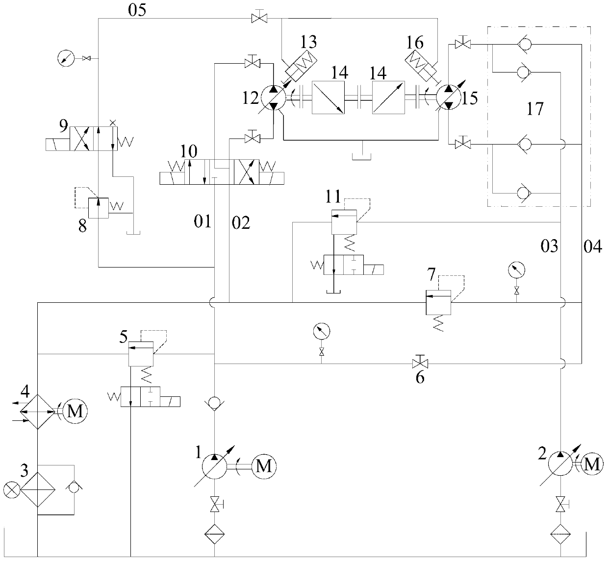
[0046] Please refer to figure 1 , the present invention will be described in further detail below in conjunction with embodiment.

[0047] Such as figure 1 As shown, the motor reducer test system of this embodiment at least includes the first oil circuit 01, the second oil circuit 02, the third oil circuit 03, the fourth oil circuit 04, the first relief valve 11, the tested motor reducer 12 and loading motor reducer 15.

[0048] Wherein, the power shaft of the loading motor speed reducer 15 is connected with the power shaft of the tested motor speed reducer 12. power shaft connection.

[...


PUM


Abstract

The invention discloses a motor decelerator test system. The motor decelerator test system comprises a tested motor decelerator, a loading motor decelerator, a first oil circuit, a second oil circuit, a third oil circuit, a fourth oil circuit and a first overflow valve, wherein a power shaft of the loading motor decelerator is connected with a power shaft of the tested motor decelerator in transmission mode, the first oil circuit is used as an oil inlet passage of the tested motor decelerator, the second oil circuit is used as an oil return passage of the tested motor decelerator, the third oil circuit is used as an oil recharging and feeding passage of the loading motor decelerator, the fourth oil circuit is used as an oil recharging and feeding passage of the loading motor decelerator and connected with the first oil circuit, and the first overflow valve is connected onto the third oil circuit and used to maintain pressure and flow rate of the third oil circuit. According to the motor decelerator test system, energy recovery efficiency of the system can be improved, and energy loss can be reduced. Furthermore, the motor decelerator test system facilitates increasing stability of running of the tested motor decelerator, and therefore can meet the needs of various tests.

Description

technical field [0001] The invention relates to the field of motor reducer testing, in particular to a motor reducer testing system. Background technique [0002] The motor reducer is the executive element in the hydraulic transmission system and the core component of the hydraulic transmission. It is widely used in various fields such as machinery, machine tools, ships, military, aerospace, petroleum, etc. Its performance directly affects and determines the hydraulic system and the whole machine. Therefore, the test of the performance characteristics of the motor reducer is very important. [0003] At present, the test of motor reducer can be divided into two kinds of loading test systems: direct loading and power recovery from the energy recovery or not. The direct loading system has simple structure, convenient and accurate loading, and little interference, but it consumes a lot of energy and is not suitable for high-power test, long-term life test and high-volume hydrau...

Claims


Application Information

Patent Timeline
IPC IPC(8): F15B19/00
Inventor 邢子平谈斌
Owner SUOTE TRANSMISSION EQUIP
Why Eureka
Try Eureka