
Image registration method based on inertial sensor and camera

An inertial sensor, image registration technology, applied in image analysis, image data processing, instruments, etc., can solve the problems of low precision, difficult to popularize handheld devices and mobile devices, and large amount of calculation.

Inactive Publication Date: 2014-04-23
NANJING UNIV OF SCI & TECH
View PDF3 Cites 40 Cited by
  • Summary
  • Abstract
  • Description
  • Claims
  • Application Information

AI Technical Summary

Problems solved by technology

[0003] Li Lichun and others proposed a three-dimensional reconstruction algorithm based on the eight-point method of the fundamental matrix [Li Lichun, Qiu Zhiqiang, Wang Kunpeng, etc. A three-dimensional reconstruction algorithm based on matching measure weighting to solve the fundamental matrix [J]. Computer Applications, 2007, 27 (10): 2530-2533], this method is complex and computationally intensive, and it is difficult to achieve real-time image processing
[0004] Zhang Yang and others proposed the FOE model to verify the translation effect of camera motion [Zhang Yang, Kaiser Wei Chi, Bo Sen. Moving object detection algorithm based on moving camera in the visible light range. Computer Vision and Pattern Recognition Studio. IEEE International Conference, 2006,130-131], this method does not consider the rotation of the camera and the internal reference matrix of the camera, the accuracy is not high
[0005] Zheng Hong and others proposed a calibration method based on active vision, which mainly uses known motion hardware platforms such as pan / tilt to provide camera motion information [Zheng Hong, Liu Zhenqiang. Self-calibration of pan / tilt camera based on accurate model[J]. Robotics, 2013.5,35(3):1994-2013], this method is difficult to popularize in hand-held devices and mobile devices due to the relatively large equipment such as the cloud platform, although it can achieve real-time performance, and the application area is limited

Method used


Image

  • Image registration method based on inertial sensor and camera
  • Image registration method based on inertial sensor and camera
  • Image registration method based on inertial sensor and camera

Examples


Embodiment Construction

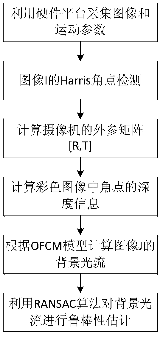
[0058] Such as figure 1 Shown, the present invention is based on the image registration method of inertial sensor and video camera, comprises the following steps

[0059] Step 1. In the hardware platform, synchronously control the camera and the inertial sensor to work, and simultaneously acquire the color images I and J, depth images I’ and J’ of the same scene, and the motion parameters of the camera, that is, the three-axis motion angular velocity [w x ,w y ,w z ] and three-axis motion acceleration [a x , a y , a z ], the specific implementation is as follows:

[0060] The hardware platform of the present invention comprises three parts: control device FPGA, inertial sensor and video camera, inertial sensor comprises gyroscope and accelerometer, video camera comprises depth image acquisition CCD and color image acquisition CCD, is used to take color image I, J and Depth images I', J', the minimum system of FPGA and inertial sensor are all fixed on the depth image acqu...


PUM


Abstract

The invention puts forward an image registration method based on an inertial sensor and a camera. The camera and the inertial sensor are synchronously controlled to operate to simultaneously acquire the color image and depth image of the same scene and the three-axis motion angular velocity and three-axis motion acceleration of the camera; Kalman filtering is utilized to carry out filtering on the three-axis motion angular velocity and the three-axis motion acceleration, the Eulerian dynamics equation is used for converting the three-axis acceleration into a Eulerian angle, the uniformly accelerated motion formula is used for converting the three-axis angular velocity into three-axis displacement, and thereby an external reference matrix of the camera is obtained; by utilizing the affine transformation relation between the color image and the depth image and the proportional relation between depth image grey value and pixel depth information, the depth information of angular points in the depth image is solved; an OFCM (Orthogonal Frequency-division Multiplexing) model is used for calculation to obtain image background optical flow; the RANSAC (Random Sample Consensus) algorithm is used for completing image registration. The calculation load of the method is low, both the real-timeness and the precision are high, and the method is applicable to hand-held devices and mobile devices.

Description

technical field [0001] The invention belongs to the field of digital image processing, and in particular relates to an image registration method based on an inertial sensor and a camera. Background technique [0002] The key issue of image registration technology is the estimation of camera motion parameters, which is usually done through camera calibration. In the prior art, methods for camera self-calibration include: [0003] Li Lichun and others proposed a three-dimensional reconstruction algorithm based on the eight-point method of the fundamental matrix [Li Lichun, Qiu Zhiqiang, Wang Kunpeng, etc. A three-dimensional reconstruction algorithm based on matching measure weighting to solve the fundamental matrix [J]. Computer Applications, 2007, 27 (10): 2530-2533], this method is complex and computationally intensive, and it is difficult to achieve real-time image processing. [0004] Zhang Yang and others proposed the FOE model to verify the translation effect of camer...

Claims


Application Information

Patent Timeline
IPC IPC(8): G06T7/00
Inventor 顾国华韩鲁刘恒建余明廖逸琪钱惟贤
Owner NANJING UNIV OF SCI & TECH
Learn More