Active optical fiber winding device and optical fiber winding method for optical fiber laser

A fiber laser and optical fiber technology, applied in the direction of lasers, laser components, laser components, etc., can solve the problems of uneven heat dissipation of optical fibers, local concentration of energy, easy damage of optical fibers, etc., to avoid randomness and heat concentration , to avoid the effect of direct contact

Inactive Publication Date: 2014-04-23
JIANGSU SKYERALASER TECH
View PDF7 Cites 7 Cited by
  • Summary
  • Abstract
  • Description
  • Claims
  • Application Information

AI Technical Summary

Problems solved by technology

The power density in the high-power fiber laser core is very high, and the heat generated is also high. During use, the active fiber must be coiled for heat dissipation. If the fiber is not coiled properly, it is easy to generate stress. It is easy to be damaged, resulting in local concentration of energy, which leads to fiber burnout. There are two methods of coiling the active fiber of fiber lasers on the market: one is the method of coiling the fiber on an aluminum cylinder, and the fiber is threaded. Coiled on a smooth cylinder, in order to prevent the optical fiber from slipping off the cylinder, the optical fiber and the optical fiber must not only be in direct and close contact, but als

Method used


Image

  • Active optical fiber winding device and optical fiber winding method for optical fiber laser
  • Active optical fiber winding device and optical fiber winding method for optical fiber laser
  • Active optical fiber winding device and optical fiber winding method for optical fiber laser

Examples


Example Embodiment

[0011] In order to make the content of the present invention more clearly understood, the present invention will be further described in detail below based on specific embodiments and in conjunction with the accompanying drawings.

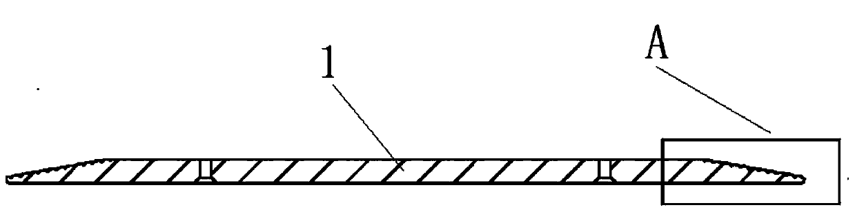
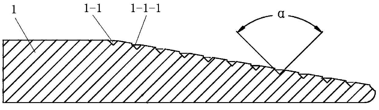
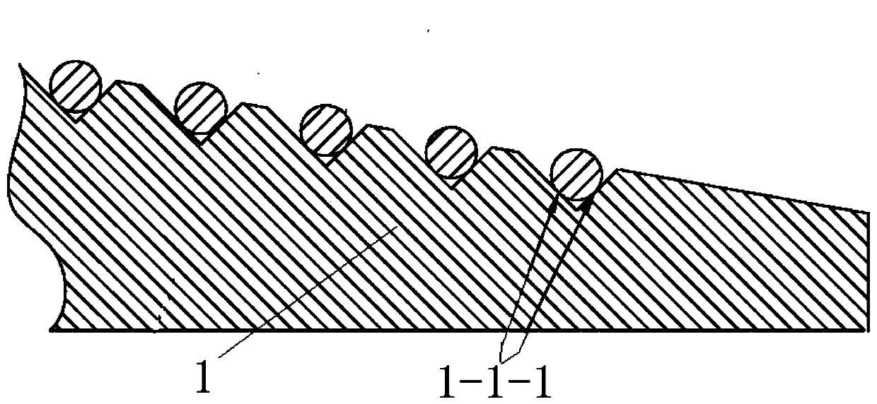
[0012] like Figure 1~3 As shown, a coiling device for an active optical fiber of a fiber laser includes a conical heat dissipation disk 1, and the conical surface of the heat dissipation disk 1 is provided with spiral grooves 1-1 arranged in a continuous manner, and the spiral grooves 1-1 There are two symmetrical groove walls 1-1-1, and the cross-sectional angle α of the two groove walls 1-1-1 is 90°, and there is a gap between adjacent optical fibers in the spiral groove 1-1 .

[0013] The heat sink 1 is made of aluminum, but not limited thereto.

[0014] like image 3 As shown, a method for coiling an optical fiber of a coiling device for an active optical fiber of a fiber laser, the steps of the method are as follows: the optical fiber is c...


PUM


Abstract

The invention discloses an active optical fiber winding device and an optical fiber winding method for an optical fiber laser. The winding device is a radiating disc with a conical shape; continuously arranged winding slots are formed in the conical surface of the radiating disc; each winding slot is provided with two symmetrical slot walls; the section included angle alpha of every two slot walls is 90 degrees; an interval is remained between the adjacent optical fibers in the winding slots. Stress caused by the direct contact between the optical fibers is avoided, a better radiating effect is achieved and the burning loss phenomenon is avoided.

Description

technical field [0001] The invention relates to a coiling device for an active optical fiber of a fiber laser and a method for coiling the optical fiber. Background technique [0002] At present, as the representative of the third-generation laser technology, fiber lasers have incomparable advantages over solid-state and gas lasers, including small size, good beam quality, high electro-optical conversion efficiency, low operating costs, and high processing accuracy; fiber lasers have been widely used It is used in the high-end manufacturing industry of material processing and mechanical processing, and the market prospect is very broad. The power density in the high-power fiber laser core is very high, and the heat generated is also high. During use, the active fiber must be coiled for heat dissipation. If the fiber is not coiled properly, it is easy to generate stress. It is easy to be damaged, resulting in local concentration of energy, which leads to fiber burnout. There...

Claims


Application Information

Patent Timeline
IPC IPC(8): H01S3/042H01S3/02G02B6/44
Inventor 田国光李丰黄伟
Owner JIANGSU SKYERALASER TECH
Why Eureka
Try Eureka