
Method for predicting current at neutral points of transformer during monopolar operation of direct current system

A transformer neutral point, DC system technology, applied in the direction of DC network circuit devices, electrical components, circuit devices, etc., can solve the problems of increasing the dimension of the calculation equation matrix, reducing the accuracy of the equation solution, increasing the complexity of calculations, etc., to achieve increased Complexity, Intuitive Modification, Efforts to Improve Applicability

Active Publication Date: 2014-04-23
STATE GRID CORP OF CHINA +2
View PDF1 Cites 1 Cited by
  • Summary
  • Abstract
  • Description
  • Claims
  • Application Information

AI Technical Summary

Problems solved by technology

The disadvantage of this method is that for the actual system with complex structure, the application of the field-circuit coupling method will increase the matrix dimension of the calculation equation, increase the complexity of the calculation and reduce the solution accuracy of the equation

Method used

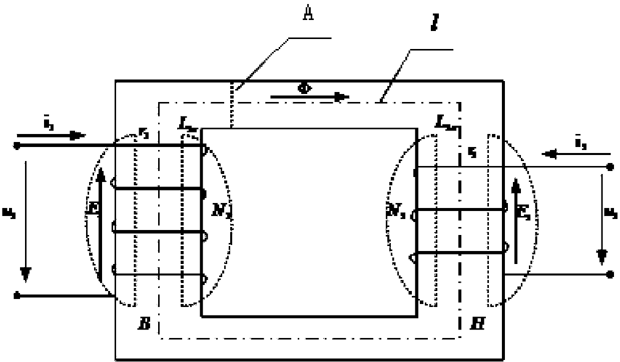
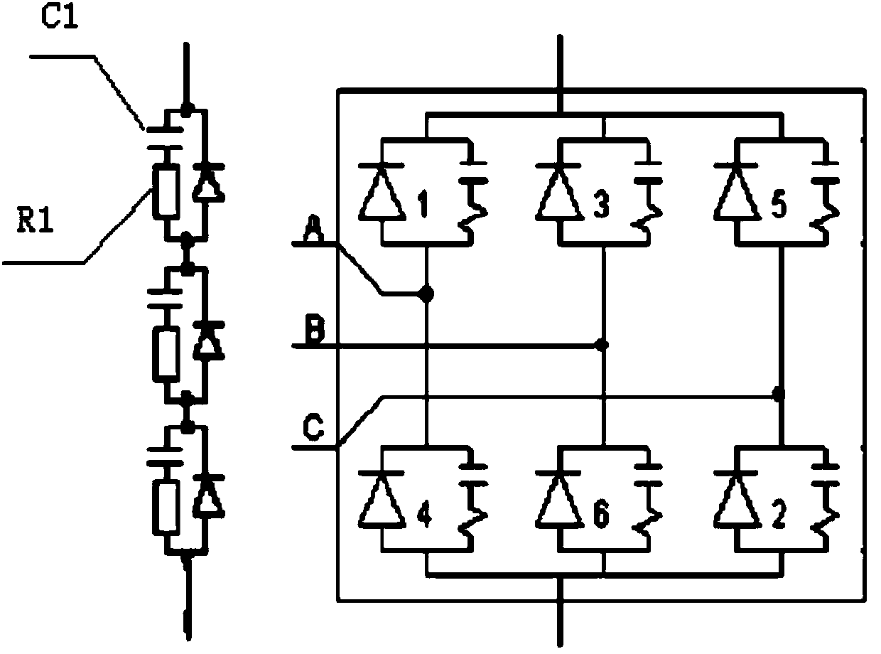

Image

  • Method for predicting current at neutral points of transformer during monopolar operation of direct current system
  • Method for predicting current at neutral points of transformer during monopolar operation of direct current system
  • Method for predicting current at neutral points of transformer during monopolar operation of direct current system

Examples


Embodiment Construction

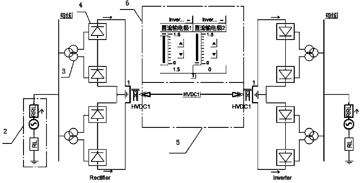
[0029] The following is attached Figure 1-4 The implementation process of the present invention will be described in detail. like figure 1 It shows that before the present invention predicts the DC current that enters the neutral point of the transformer when the HVDC power transmission system is in the unipolar operation mode, it should first obtain the topological structure diagram of the AC-DC power transmission network and the operating parameters of the system, and then proceed according to the following steps : The first step is to calculate the self-resistance of the DC grounding electrode and the grounding grid at this place, and the self-resistance of the grounding grid is taken as the grounding resistance of the grounding body; the second step is to calculate the mutual resistance of the DC grounding electrode and the grounding grid at this place. The size reflects the influence of the soil between the two ground electrodes on the passage of DC current; the third s...


PUM

PropertyMeasurementUnit
Capacitanceaaaaaaaaaa
Resistanceaaaaaaaaaa

Abstract

The invention discloses a method for predicting current at neutral points of a transformer during the monopolar operation of a direct current system. The method is characterized in that after an alternating current and direct current transmission network topologic structure chart and system running parameters of the neutral points of the transformer to be detected during the monopolar operation of the direct current system are obtained, the method is implemented by the following steps of 1, calculating the self resistance of direct current grounding electrodes and grounding grids at the neutral points; 2, calculating the mutual resistance of the direct current grounding electrodes and the grounding grids at the neutral points; 3, establishing an alternating current and direct current transmission system model of the neutral points based on the self resistance, the mutual resistance and the alternating current and direct current transmission network topologic structure chart and the system running parameters of the neutral points by utilizing PSCAD (power system computer aided design); 4, running the model to measure current at each neutral point of the transformer as a predicted value. According to the method, the concept of the mutual resistance is disclosed to convert a complex current field problem into an easy-to-solve circuit problem; the model is a visual model, so that a prediction system is more intuitive, and can be conveniently correspondingly modified according to an actual alternating current and direct current hybrid system, and the applicability of the prediction scheme is improved.

Description

technical field [0001] The invention relates to a method for predicting the neutral point current of a transformer during unipolar operation of a direct current system, in particular to a method for predicting the direct current flowing into the neutral point of a transformer when a high-voltage direct current transmission system is in a unipolar operation mode. Background technique [0002] The operation modes of DC transmission system mainly include unipolar metal loop mode, single pole ground loop mode and bipolar mode. When one pole breaks down or needs to be out of operation for maintenance, the other pole becomes a single-pole working mode, using the earth or seawater as a circuit to continue to operate. DC current field. Furthermore, a large potential difference will be formed between the AC substations near the converter station, so that the DC component flows through the winding of the neutral point grounding transformer in the substation. Therefore, before DC tra...

Claims


Application Information

Patent Timeline
IPC IPC(8): H02J1/00
Inventor 全江涛郭倩雯阮羚林湘宁邓万婷鲁俊生
Owner STATE GRID CORP OF CHINA
Learn More