Water cooling plate for heat dissipation of high-power electrical heating element

A technology for heating elements and water-cooling plates, applied in electrical components, electrical solid devices, circuits, etc., can solve the problems of unfavorable water-cooled plate heat exchange efficiency, difficulty in reducing fin spacing, and difficulty in increasing fin thickness, etc. The effect of heat dissipation efficiency, increased disturbance, and strong heat dissipation capacity

Inactive Publication Date: 2014-04-23
周细文 +1
View PDF7 Cites 8 Cited by
  • Summary
  • Abstract
  • Description
  • Claims
  • Application Information

AI Technical Summary

Problems solved by technology

However, high fin height (≥10mm) and too small fin spacing (≤1mm) are difficult to process in actual production, and the processing efficiency is relatively low
[0005] 2. Utilizing formed cooling fins: Although the processing difficulty of the water-cooled plate is reduced and the water-cooling heat transfer coefficient is increased to a certain extent, it is difficult to increase the thickness of the fins due to the limitation of the processing technology of the formed fins, and the corresponding fin spacing is also It is difficult to reduce, which is not conducive to improving the heat transfer efficiency of the water-cooled plate
[0006] 3. Disturbance of the coolant in the flow channel: the measures to increase the disturbance of the coolant in the previous water-cooled plate scheme mainly focused on the shape of the fins or turbulators, and there was no disturbance to the coolant formed by the cooperative relationship between the fins of the upper and lower plates. flow has been tested

Method used


Image

  • Water cooling plate for heat dissipation of high-power electrical heating element
  • Water cooling plate for heat dissipation of high-power electrical heating element
  • Water cooling plate for heat dissipation of high-power electrical heating element

Examples


Embodiment Construction

[0036] The present invention will be further described below in conjunction with the accompanying drawings and specific embodiments.

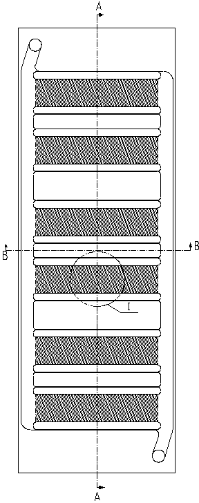
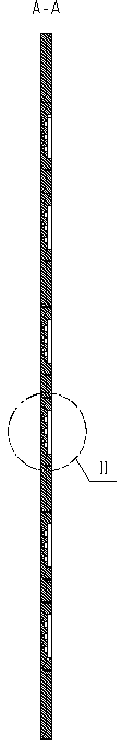
[0037] The new fin arrangement form high-power heat dissipation water-cooled plate, including the upper plate 6 with fins and the lower plate 7 with fins, is a heat dissipation substrate welded together by vacuum brazing, and the surface of the substrate is provided with threaded holes 10 for installing IGBTs , a water pipe joint 5 is also installed, and the threaded hole is inlaid with a wire thread sleeve to meet the torque requirements for installation.

[0038] The upper and lower plate fins are formed by milling grooves on the upper and lower plates. First, the height h of the fins of the upper and lower plates is given 1 , h 2 with spacing. (also both the milling groove depth and groove spacing), when machining the upper plate fin area, the tool feed direction and the upper plate form a certain angle (θ 1 , θ 2 ), the processing is c...


PUM


Abstract

The invention provides a water cooling plate for heat dissipation of a high-power electrical heating element. The water cooling plate comprises an upper plate (6) with upper fins (8) and a lower plate (7) with lower fins (4); and the upper plate (6) with the upper fins (8) and the lower plate (7) with the lower fins (4) and a main flow channel are welded to form an integrated one, thereby forming a cooling medium flow channel. In addition, the upper plate and the lower plate respectively include upper plate slots (13) and lower plate slots (12), wherein the upper plate slots (13) and the lower plate slots (12) are formed by milling. And the upper fins (8) and the lower fins (4) are arranged in a staggered mode at certain angles in the flow channel. With the water cooling plate, the cooling liquid disturbance in the flow channel is enhanced. The heat dissipation efficiency is high; and the processing technology is relatively simply. And the water blocking can be controlled in a reasonable range.

Description

technical field [0001] The invention relates to water cooling and heat dissipation technology, in particular to a water cooling plate for cooling a power module of a high-power converter or a power module of a high-power AC and DC test power supply. Background technique [0002] During the design process of the water-cooled plate, the design of the internal flow channel and the cooling fins of the water-cooled plate are the main factors affecting the heat dissipation effect. Existing heat dissipation fins of water-cooled plates are in the form of straight, zigzag, porous and so on. Using the above-mentioned fin form, the processing technology of the water-cooled plate includes milling the fin directly in the flow channel and using the formed fin to fill the flow channel in the heat dissipation area, and then welding it into one body. [0003] However, the existing water-cooled plate runners and fin processing schemes have the following problems: [0004] 1. Fins are milled...

Claims


Application Information

Patent Timeline
Patent Type & Authority Applications(China)
IPC IPC(8): H05K7/20H01L23/473
CPCH01L2924/0002
Inventor 周细文
Owner 周细文
Why Eureka
Try Eureka