Al technical title is built by PatSnap Al team. It summarizes the technical point description of the patent document.
A spot welding machine and precise technology, applied in welding equipment, soldering irons, tin feeding devices, etc., can solve the problems of broken skeleton, unsmooth solder joints, exposed leads of pins, etc., to achieve compact structure, avoid defects, and reasonable design. Effect
Inactive Publication Date: 2014-04-30
惠涌
View PDF10 Cites 8 Cited by
Summary
Abstract
Description
Claims
Application Information
AI Technical Summary
This helps you quickly interpret patents by identifying the three key elements:
Problems solved by technology
Method used
Benefits of technology
Problems solved by technology
[0002] The soldering methods currently used are mainly automatic soldering machines, manual soldering with soldering irons, manual soldering in tin furnaces, and spot welding. However, these traditional soldering methods are only 8mm in size, pure bakelite skeleton, without pins, and the size of the welding area is only 0.5mm. For these products, the soldering of these products is likely to cause damage to the skeleton, rough solder joints, exposed wire ends on the pins, and the copper wires on the pins cannot be covered with tin all around to form full tin spots
Method used
Image
Click on the blue label to locate the original text in one second.
Reading with bidirectional positioning of images and text.
Examples
Embodiment Construction
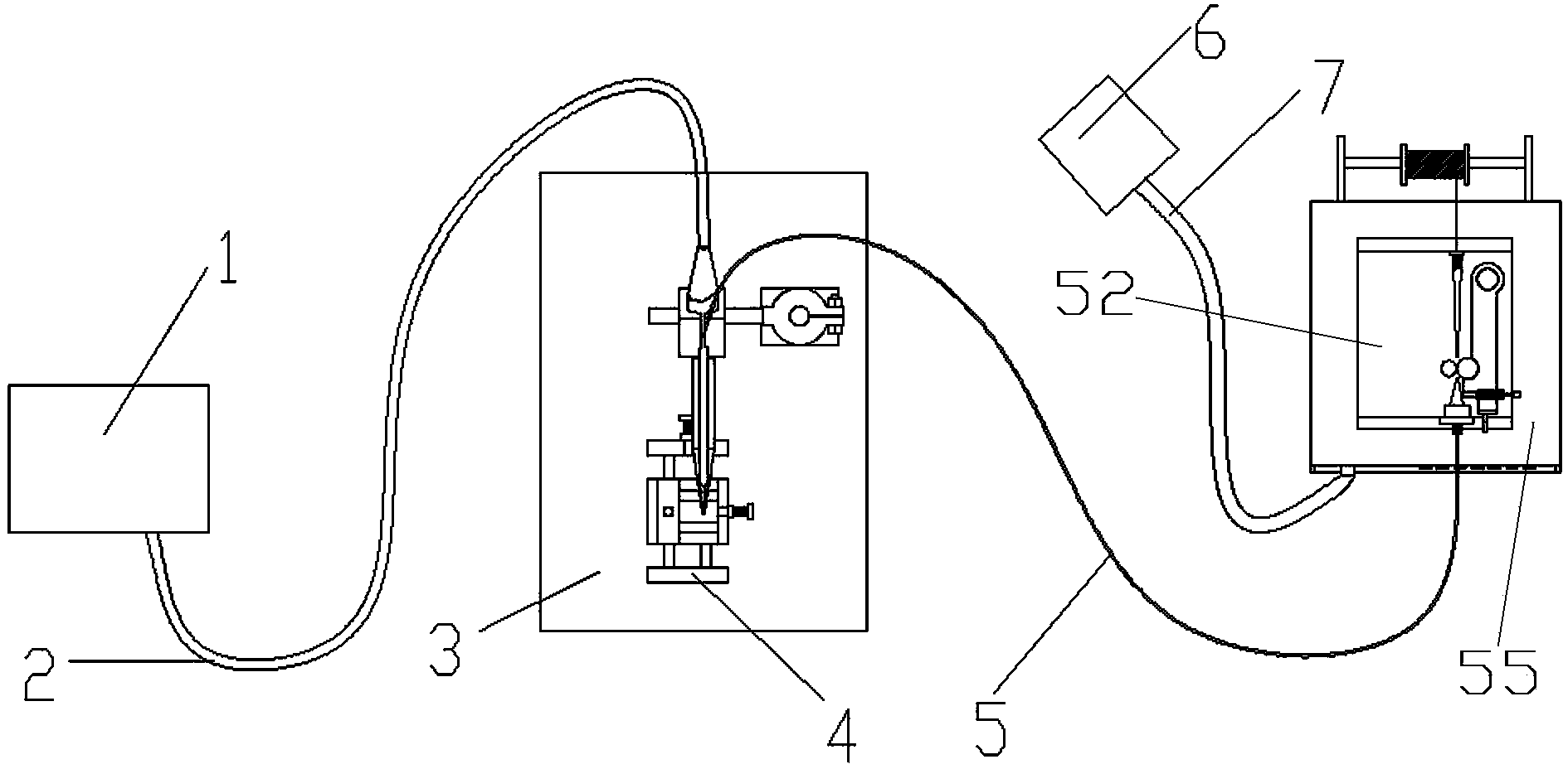
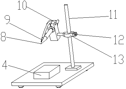
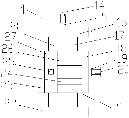
[0021] Refer to attached Figure 1~6 , The precision spot welding machine includes a soldering iron controller, an automatic tin wire device, and a soldering operation device.
[0022] The soldering iron controller has a control box, the control box is equipped with an operation panel, and the operation panel is equipped with a switch 34, a control line interface (soldering iron tip wire interface) 30, a temperature display 29, a temperature setting key 31, a temperature drop key 32, and a temperature increase key 33. A microcomputer controller is installed in the control box. Temperature display 29 adopts commercially available liquid crystal display. Microcomputer controller adopts commercially available microcomputer controller. The soldering iron controller can be purchased, the model is QUICK 203H lead-free intelligent high-frequency welding station.
[0023] The tin wire device that goes out automatically is made of tin wire installation frame 56, tin wire control box...
PUM
Abstract
The invention relates to precision spot equipment suitable for no-pin needle type miniature frameworks and products with small welding spots and provides a precision spot welder. The precision spot welder is suitable for precision frameworks and the occasions that welding spots are required to be smooth, plump and small and the requirements for welding spot positions are high. The precision spot welder comprises a soldering iron control instrument, an automatic tin wire discharge device and a tin soldering operating device. The soldering iron control instrument is provided with a control box, the control box is provided with an operation panel, and a microcomputer controller is arranged in the control box; the automatic tin wire discharge device is formed by a tin wire mounting rack, an automatic tin wire discharge control box, a tin wire feed nozzle, a locating nut, a tin wire transmission wheel, a tin wire transmission motor, a tin wire clamping wheel, a tin wire passing nozzle, an adjusting spanner, a spring, a first screw, a connecting piece, a vertical piece at the front end of the connecting piece, a mounting table, a tin wire guide pipe and a pedal. The tin soldering operating device is formed by a base, a support, a movable flame, an installation block, a locating screw, a tin wire discharge nozzle, a soldering iron head and a tin soldering product locating movable device.
Description
technical field [0001] The precision spot welding machine of the present invention relates to a kind of precision spot welding equipment suitable for products with no needle-type micro-skeleton and small solder joints. It is suitable for precision skeletons, where the solder joints are required to be smooth and full, and the solder joints are small, and the requirements for the position of the solder joints are relatively high. Background technique [0002] The soldering methods currently used are mainly automatic soldering machines, manual soldering with soldering irons, manual soldering in tin furnaces, and spot welding. However, these traditional soldering methods are only 8mm in size, pure bakelite skeleton, without pins, and the size of the soldering area is only 0.5mm. For the products of these products, the welding of these products is easy to cause the skeleton to be damaged, the solder joints are not smooth, the pins are exposed, and the copper wires on the pins can...
Claims
Application Information
Patent Timeline
Application Date:The date an application was filed.
Publication Date:The date a patent or application was officially published.
First Publication Date:The earliest publication date of a patent with the same application number.
Issue Date:Publication date of the patent grant document.
PCT Entry Date:The Entry date of PCT National Phase.
Estimated Expiry Date:The statutory expiry date of a patent right according to the Patent Law, and it is the longest term of protection that the patent right can achieve without the termination of the patent right due to other reasons(Term extension factor has been taken into account ).
Invalid Date:Actual expiry date is based on effective date or publication date of legal transaction data of invalid patent.