Check patentability & draft patents in minutes with Patsnap Eureka AI!

Tin slag fishing device

A salvage device and tin slag technology, applied in auxiliary devices, metal processing equipment, manufacturing tools, etc., can solve the problems of inconvenient use of tin slag treatment devices, and achieve the effect of improving space utilization, improving effect, and good protection.

Inactive Publication Date: 2014-04-30
View PDF11 Cites 8 Cited by
  • Summary
  • Abstract
  • Description
  • Claims
  • Application Information

AI Technical Summary

Problems solved by technology

[0005] The technical problem to be solved by the present invention is to provide a tin slag fishing device aiming at the inconvenient defect of the existing tin slag processing device

Method used


Image

  • Tin slag fishing device
  • Tin slag fishing device
  • Tin slag fishing device

Examples


Embodiment Construction

[0028] In order to make the technical problems, technical solutions, and beneficial effects solved by the present invention clearer, the following further describes the present invention in detail with reference to the accompanying drawings and embodiments. It should be understood that the specific embodiments described herein are only used to explain the present invention, but not to limit the present invention.

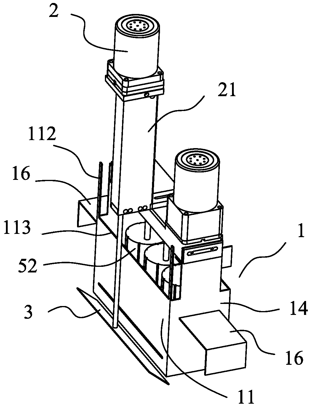
[0029] In the description of the present invention, it needs to be understood that the directions or positional relationships indicated by the terms "upper", "lower", "top", "bottom", "inner", "outer", etc. are based on the attached figure 1 The orientation or positional relationship shown is only for the convenience of describing the present invention and simplifying the description, rather than indicating or implying that the device or element referred to must have a specific orientation, be constructed and operated in a specific orientation, and therefore cannot be un...


PUM

PropertyMeasurementUnit
angleaaaaaaaaaa

Abstract

The invention provides a tin slag fishing device which comprises a tin slag collecting groove, a driving motor, a transmission mechanism and a slag fishing sheet. The tin slag collecting groove is defined by four side walls, at least one side wall of the four side walls is a vertical side wall, the driving motor is used for driving the slag fishing sheet to be attached to the vertical side wall to conduct vertical reciprocating movement through the transmission mechanism, an included angle is formed between the slag fishing sheet and the vertical side wall, and fished tin slag falls into the tin slag collecting groove along the vertical side wall. The tin slag collecting groove is a zone defined by the four side walls with the periphery closed. When the tin slag fished by the slag fishing sheet is gathered in the zone with the periphery closed, the tin slag cannot be diffused to other places and the good tin slag collecting effect is achieved. The tin slag collecting groove can be conveniently used in cooperation with a stirring mechanism and a stannic oxide reducing agent and the tin slag treatment effect is greatly improved.

Description

Technical field [0001] The invention belongs to the technical field of wave soldering, and in particular relates to a wave soldering tin slag processing device. Background technique [0002] The existing wave soldering machine uses the tin solder melted in the tin bath to deliver the tin liquid to the nozzle through the drive device to form a wave crest, and solder the circuit board (PCB board) that carries the electronic components. During work, as the tin liquid is sprayed from the nozzle in the tin liquid tank, part of the solder meets the air and oxidizes to form tin dross. At the same time, the surface of the tin liquid in the tin liquid tank is also exposed to the air, oxidizing to form tin Slag, tin slag entrained good metals are constantly produced and floated out, causing the slag to accumulate more and more, layered on top of each other, becoming thicker and thicker, affecting the liquid surface flow, and even causing overflow. [0003] In order to solve the above-mentio...

Claims


Application Information

Patent Timeline
Patent Type & Authority Applications(China)
IPC IPC(8): B23K3/08
CPCB23K1/085B23K3/08
Inventor 严支农胡小平
Features
  • R&D
  • Intellectual Property
  • Life Sciences
  • Materials
  • Tech Scout
  • Unparalleled Data Quality
  • Higher Quality Content
  • 60% Fewer Hallucinations
Learn More