Fillet weld recognition device and welding control method thereof

A technology for identifying devices and control methods, applied in auxiliary devices, digital controls, welding equipment, etc., can solve problems such as low welding efficiency, cumbersome control process, and complex algorithms, so as to achieve convenient weld identification, accurate determination of welds, The Effect of Simplified Calculation Algorithm for Weld Seam Recognition

Active Publication Date: 2014-04-30
浙江菲达科技发展有限公司
View PDF6 Cites 23 Cited by
  • Summary
  • Abstract
  • Description
  • Claims
  • Application Information

AI Technical Summary

Problems solved by technology

[0002] The methods of welding seam recognition mainly include manual control, robot teaching or offline programming to identify the welding seam path. During the welding process, the preset actions are repeated. This method of welding seam recognition is only applicable to the same batch of batches. The welding work of the welding program, but in actual production, when a single weld with different trajectories needs to be welded, it is necessary to continuously adjust the program, resulting in low welding efficiency
[0003] There is also a Chinese invention patent with a publication number of CN101559512 disclosing a method for detecting and controlling the welding trajectory of flat butt welds based on laser ranging. The information of the weld outline is obtained by horizontal scanning of the laser sensor, and the weld is reconstructed after effective filtering. Realize the three-dimensional inspection of the weld seam, and realize automatic welding based on the weld seam information, but because the weld seam information is only scanned by the laser sensor, the algorithm of the processing process is relatively complicated, and the control process is relatively cumbersome

Method used


Image

  • Fillet weld recognition device and welding control method thereof
  • Fillet weld recognition device and welding control method thereof
  • Fillet weld recognition device and welding control method thereof

Examples


Embodiment Construction

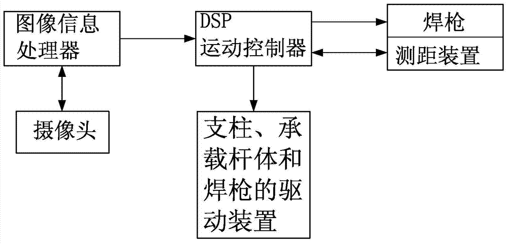
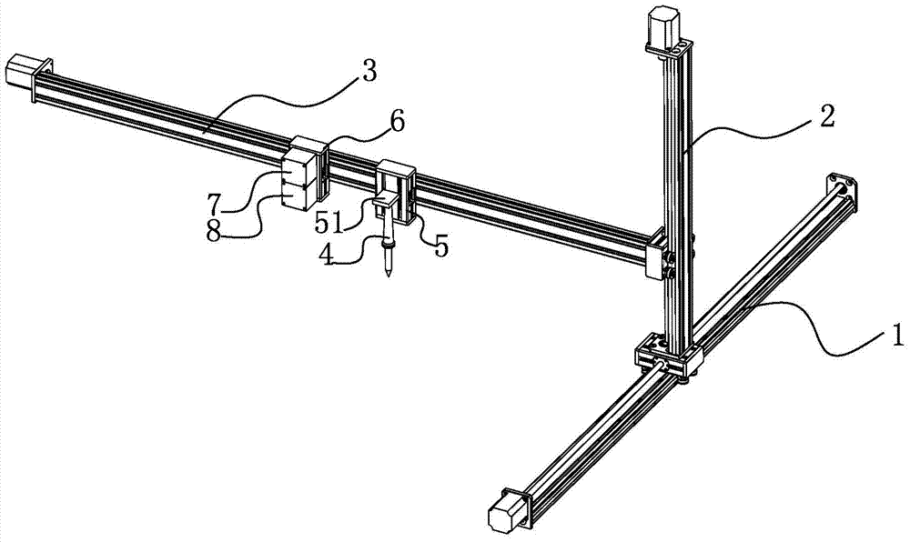
[0024] Such as Figure 1-2 As shown, a fillet weld recognition device consists of two parts, one is the image information acquisition and processing part including the image information processor and camera, and the other is the mechanical part with a frame as the cylinder , wherein the camera collects the image information of the weld and sends it to the image information processor, the image information processor communicates with a DSP motion controller, and the frame consists of a crossbar 1 as a base, a pillar 2 vertically slidably connected to the crossbar 1 and It consists of a bearing rod body 3 slidably connected to the pillar. The welding torch 4 is slidably connected to the bearing rod body 3. The distance measuring device is also slidably connected to the bearing rod body 3. The distance measuring device sends a weld distance signal to the DSP motion controller. The DSP motion controller sends control signals to the driving devices of the pillar 2 , the carrying ro...


PUM


Abstract

The invention discloses a fillet weld recognition device and a welding control method thereof and belongs to the technical field of automatic welding. The fillet weld recognition device comprises an image frame, an image information processor, a camera and a DSP (digital signal processor) motion controller. The camera collects weld image information and transmits the same to the image information processor; the image information processor transmits weld coordinate signals to the DSP motion controller which controls motion of a welding gun; the welding gun and a distance measuring device are arranged on the image frame, and the distance measuring device transmits distance signals to the DSP motion controller. The welding control method thereof includes that the image information is collected through the camera, coarse positioning of welding positions is completed through the image information processor, the distance signals of the weld coordinate signals and an infrared distance measuring device are inputted to the DSP motion controller for accurate positioning, and the welding gun performs welding according to guidance and calibration of the DSP motion controller.

Description

technical field [0001] The invention relates to the technical field of automatic welding, in particular to a fillet weld identification device based on infrared ranging and a welding control method thereof. Background technique [0002] The methods of welding seam recognition mainly include manual control, robot teaching or offline programming to identify the welding seam path. During the welding process, the preset actions are repeated. This method of welding seam recognition is only applicable to the same batch of batches. The welding work of the welding program, but in actual production, when a single weld with different trajectories needs to be welded, it is necessary to continuously adjust the program, resulting in low welding efficiency. [0003] There is also a Chinese invention patent with a publication number of CN101559512 disclosing a method for detecting and controlling the welding trajectory of flat butt welds based on laser ranging. The information of the weld ...

Claims


Application Information

Patent Timeline
Patent Type & Authority Applications(China)
IPC IPC(8): B23K9/127G05B19/19
CPCB23K9/0956B23K9/1274B23K37/00G05B19/19
Inventor 章涵泮云飞遇彬韩乐陈佳郭林姚雪源
Owner 浙江菲达科技发展有限公司
Why Eureka
Try Eureka