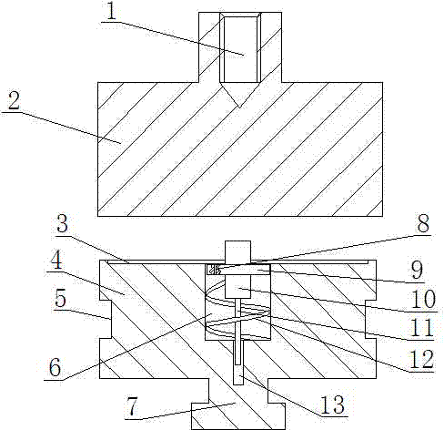
Welding device for positioning welding nut
A welding device and positioning welding technology, used in auxiliary devices, welding equipment, auxiliary welding equipment, etc., can solve the problems of large welding position deviation, low efficiency, poor effect, etc., and achieve high welding efficiency, high position accuracy, and good effect. Effect
- Summary
- Abstract
- Description
- Claims
- Application Information
AI Technical Summary
Problems solved by technology
Method used
Image
Examples
Embodiment 1
[0016] Such as figure 1 The shown welding device for positioning welding nuts includes an upper pressing block 2 and a lower supporting block 4 arranged relatively up and down, the upper end of the upper pressing block 2 is provided with a connecting column, and the connecting column is provided with a threaded connection hole 1 ; The middle part of the lower support block 4 is provided with a cylindrical spring cavity 6, the spring cavity 6 is provided with a spring 12, the upper end of the spring 12 is connected with a positioning post 10, and the middle part of the positioning post 10 is provided with a retaining ring 9. The lower end surface of the supporting block 4 is provided with a trapezoidal connecting block 7 .
[0017] In this embodiment, the upper pressing block 2 is connected to the upper end of the welding machine through the threaded connection hole 1, and the lower supporting block 4 is connected to the workbench of the welding machine through the trapezoidal ...
Embodiment 2
[0019] This embodiment adds the following structure on the basis of Embodiment 1: the lower end of the positioning column is provided with a limit straight rod 11, and the lower support block 4 is provided with a straight rod guide hole 13 in the middle of the bottom end of the spring cavity 6. The lower end of the limiting straight rod 11 is located in the straight rod guide hole 13 .
[0020] The limiting straight rod 11 in this embodiment can not only ensure that the positioning column 10 can remain vertical when moving downward, and ensure the welding position of the nut, but also play a good guiding role in the up and down movement of the positioning column 10, Prevent the retaining ring 9 from being stuck, and also protect the spring 12 at the same time, avoid the spring 12 from being damaged due to excessive pressure, and prolong the service life of the spring 12 .
Embodiment 3
[0022] In this embodiment, the retaining ring is optimized on the basis of Embodiment 1 or Embodiment 2, specifically: the retaining ring 9 is provided with a through hole 8, and the through hole 8 communicates the spring cavity 6 at the lower end of the retaining ring 9 with the outside world .
[0023] In this embodiment, in order to prevent the air in the spring cavity 6 at the lower end of the retaining ring 9 from not circulating, the elastic change of the spring 12 is slow and affect the movement of the positioning post 10, and at the same time, in order to increase the adjustment effect of the positioning post 10 and the retaining ring 9 on the welding nut, Therefore, a through hole 8 is provided on the retaining ring 9 to connect the spring cavity 6 at the lower end of the retaining ring 9 with the outside world, so as to ensure equal internal and external pressure and normal movement of the positioning column 10 .
PUM
 Abstract
Description
Claims
Application Information
 - R&D
- Intellectual Property
- Life Sciences
- Materials
- Tech Scout
- Unparalleled Data Quality
- Higher Quality Content
- 60% Fewer Hallucinations
Browse by: Latest US Patents, China's latest patents, Technical Efficacy Thesaurus, Application Domain, Technology Topic, Popular Technical Reports.
© 2025 PatSnap. All rights reserved.Legal|Privacy policy|Modern Slavery Act Transparency Statement|Sitemap|About US| Contact US: help@patsnap.com

