Rotary Jet Stator Recoil Turbine

A technology of spraying the stator and penetrating, applied in the field of turbines, can solve the problems of slow rotation speed of compressed air turbines, difficult to obtain effective application, unable to meet industrial production, etc., and achieves simple structure, stable operation, and energy conversion. Efficient effect

Inactive Publication Date: 2016-06-22
石智勇
View PDF8 Cites 0 Cited by
  • Summary
  • Abstract
  • Description
  • Claims
  • Application Information

AI Technical Summary

Problems solved by technology

[0003] At present, turbines using compressed air as the working medium are relatively rare. The main reason is that compressed air turbines have slow speed and low conversion efficiency, which cannot meet the requirements of industrial production, especially in the field of automotive power devices. There is basically a blank in the power plant of the type turbine, so it is of great significance to develop a compressed air type turbine that is pollution-free, has a wide source of working fluid, and has high working efficiency in the field of automotive power devices.
Publication No. is a Chinese patent of 1912351, which discloses a jet jet engine, which is sequentially connected by an air inlet, a runner, and a cylinder to form a rotating body on the same axis, and an air passage check valve and a compression chamber are installed on the runner. , combustion chamber, nozzle, if need to output higher power, need to inject larger air flow, the overall conversion efficiency is low, it is difficult to get effective application in actual operation, therefore, if need to develop compressed air turbine machine must be Improvements to current turbines

Method used


Image

  • Rotary Jet Stator Recoil Turbine
  • Rotary Jet Stator Recoil Turbine

Examples


Embodiment Construction

[0017] The present invention will be further elaborated below with regard to specific embodiment:

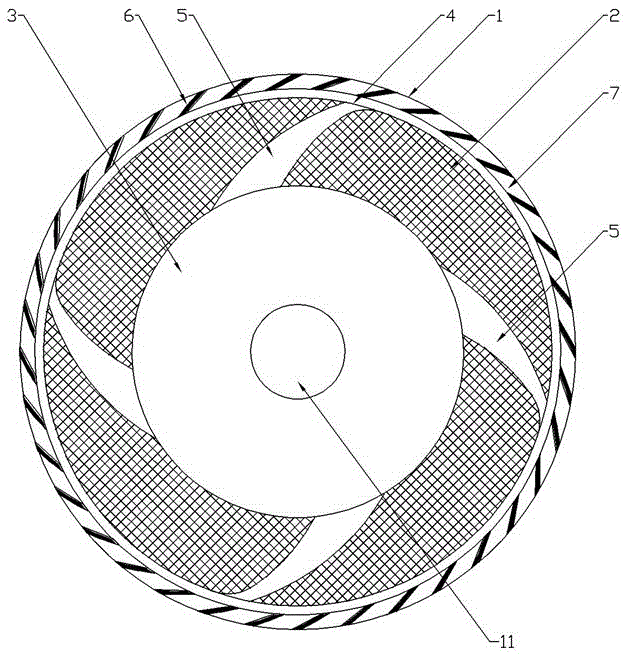
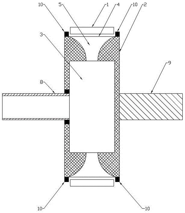
[0018] like figure 1 and figure 2 As shown, the present invention includes a stator 1 and a rotor 2 arranged in the stator 1, the rotor 2 is provided with an expansion split chamber 3, and at least one nozzle 4 is provided on the outer circumference of the rotor 2. The rotor 2 is also provided with a spout 5 that communicates with the expansion split chamber 3 and the spout 4, and the inner circumferential surface of the stator 1 is evenly provided with a number of curved teeth 6 that match the spray direction of the spout 4 Between the adjacent curved teeth 6 there is a tooth groove 7 that is compatible with the nozzle 4, and one side of the rotor 2 rotates coaxially and is sealed with a guide that communicates with the expansion split chamber 3. The other side of the flow pipe 8 and the rotor 2 is coaxially fixed with a rotor transmission shaft 9 . In this embodiment, the ...


PUM


Abstract

The invention discloses a turbine, and aims to provide a rotary spraying stator backflushing turbine which is simple in structure, high in energy conversion efficiency and safe and stable in operation. The rotary spraying stator backflushing turbine comprises a stator (1) and a rotor (2), wherein an expansion flow-splitting chamber (3) is arranged inside the rotor (2), at least one nozzle (4) is arranged on the outer circumference of the rotor (2), a spraying channel (5) communicated with the expansion flow-splitting chamber (3) and the nozzle (4) is further arranged inside the rotor (2), a plurality of bent teeth (6) matched with the spraying direction of the nozzle (4) are evenly arranged on the inner side of the stator (1), a tooth groove (7) matched with the nozzle (4) is formed between every two adjacent bent teeth (6), a flow guiding pipe communicated with the expansion flow-splitting chamber (3) is coaxially rotationally arranged on one side of the rotor (2) in a sealed mode, and a rotor transmission shaft is coaxially fixedly arranged on the other side of the rotor (2). The rotary spraying stator backflushing turbine is applied to the technical field of turbines.

Description

technical field [0001] The invention relates to a turbine, in particular to a rotary spray stator recoil turbine. Background technique [0002] A turbine is a machine that converts the energy contained in a fluid working medium into mechanical work, also known as a turbine or turbine. The working conditions of the turbine and the working fluid used are different, and its structure is also varied, but the basic principles are similar. The most important part of a turbine is a rotating part, the rotor, which is installed on the turbine shaft. The energy of the fluid passing through the nozzle in the flow is converted into a function. When the fluid flows through the rotor, the fluid impacts the rotor and drives the rotor to rotate. , so as to drive the turbine shaft to rotate and output mechanical work. The working medium of the turbine can be gas, such as: steam, gas, air and other gases or mixed gases; it can also be liquid, such as: water, oil or other liquids. Water tur...

Claims


Application Information

Patent Timeline
Patent Type & Authority Patents(China)
IPC IPC(8): F01D9/02
Inventor 石智勇
Owner 石智勇
Why Eureka
Try Eureka