Device for coating electrically conductive wires

A wire and coating technology, which is applied to the surface coating liquid device, conductor/cable insulation, coating, etc., can solve the problem of insufficient connection quality, achieve less space, low energy consumption, high The effect on process safety

Inactive Publication Date: 2014-04-30
AUMANN GMBH
View PDF9 Cites 4 Cited by
  • Summary
  • Abstract
  • Description
  • Claims
  • Application Information

AI Technical Summary

Problems solved by technology

Both methods lead to problems due to the high proportion of insulating material when using wires produced according to the described method
This insulating material also evaporates during soldering or welding, so that the quality of the connection is often insufficient

Method used


Image

  • Device for coating electrically conductive wires

Examples


Embodiment Construction

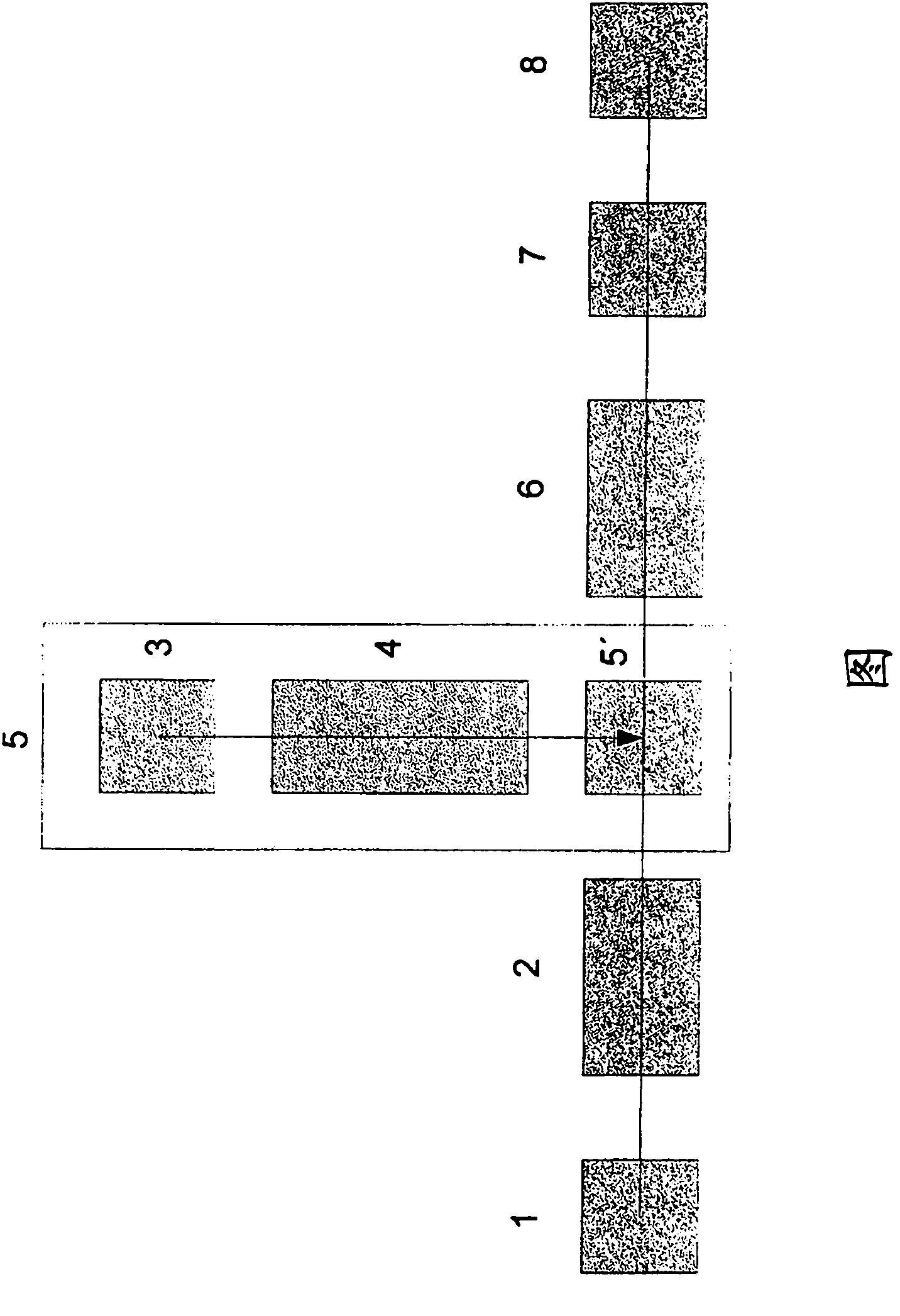
[0035] The supply of the wire to be coated takes place via a unit 1 . The bare wire is transported to unit 2 where the wire is pre-treated. The pretreated wire is then guided through unit 5 . The application of the insulating coating material takes place in this unit.

[0036] The unit 5 is designed as a so-called transverse spray head. The transverse nozzle is connected to the extruder 4 . In the extruder 4 the plastic pellets from the storage container 3 are melted. The melted plastic pellets are then evenly applied to the wire by a transverse spray head.

[0037] The transverse jet 5 comprises a connection to the extruder outlet, a wire guide system centrally arranged at right angles or at an angle to the extruder screw axis.

[0038] The material is applied to the wire around the wire guide system by means of distribution channels and nozzle guide means.

[0039] The distribution channels are designed in such a way that the material is distributed evenly around the c...


PUM


Abstract

The present invention relates to a device for coating electrically conductive wires, comprising a plurality of units in the following arrangement: a unit (1) for feeding the wires, a unit (2) for the pretreatment of the wires, a unit (5) for applying a coating medium, a unit (6) for the aftertreatment of the coated wires, and a unit (8) for winding up the coated wire.

Description

technical field [0001] The present invention relates to apparatus and methods for applying one or more layers of coating media to electrically conductive wires. Background technique [0002] According to the prior art, winding coils, in particular for electrical coils, are provided with an insulating coating. For this purpose, for example, a wire insulating varnish is applied to the wire and cured. This step can be repeated between once and more than 30 times in order to ensure defect-free insulation. Thereafter the lacquered wire is wound onto spools. [0003] Devices for carrying out the method are described in the prior art, for example in DE3741328C2, EP196017B1, WO2005 / 082548A2. [0004] What is common to the painting methods known so far is that the wire can be softened and annealed in a so-called tempering furnace (Glühe) before painting and that drawing lubricant residues can be removed. The lacquer is then applied either by means of a scraper nozzle or by means ...

Claims


Application Information

Patent Timeline
Patent Type & Authority Applications(China)
IPC IPC(8): B05D1/26B05D7/20B05D3/02
CPCB05D7/20B05D3/0218B05D1/265H01B13/065H01B13/145B05D3/0254
Inventor H·鲁道夫H·内德曼
Owner AUMANN GMBH
Why Eureka
Try Eureka