Backwater valve and fluid power energy-saving water pump

A technology of fluid power and reverse flow valve seat, which is applied in the direction of pressure pumps, components of pumping devices for elastic fluids, liquid fuel engines, etc., and can solve problems such as small compression force, so as to increase gas compression force and improve ejection The effect of speed and water output and increase of head height

Active Publication Date: 2016-03-09
付兰荣 +1
View PDF8 Cites 0 Cited by
  • Summary
  • Abstract
  • Description
  • Claims
  • Application Information

AI Technical Summary

Problems solved by technology

[0006] The invention provides a reverse water valve and a fluid power energy-saving water pump, which are used to solve the problem that the gas in the air tank is less compressed in the existing water pump, and realize the improvement of the head height of the water pump

Method used


Image

  • Backwater valve and fluid power energy-saving water pump
  • Backwater valve and fluid power energy-saving water pump
  • Backwater valve and fluid power energy-saving water pump

Examples


Embodiment 1

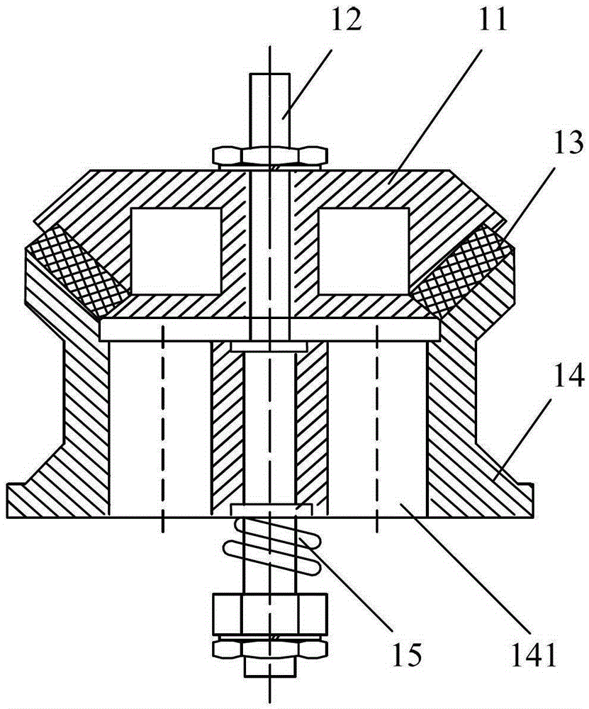
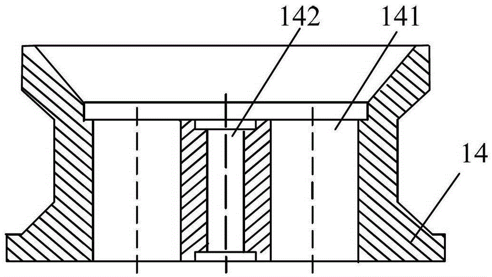
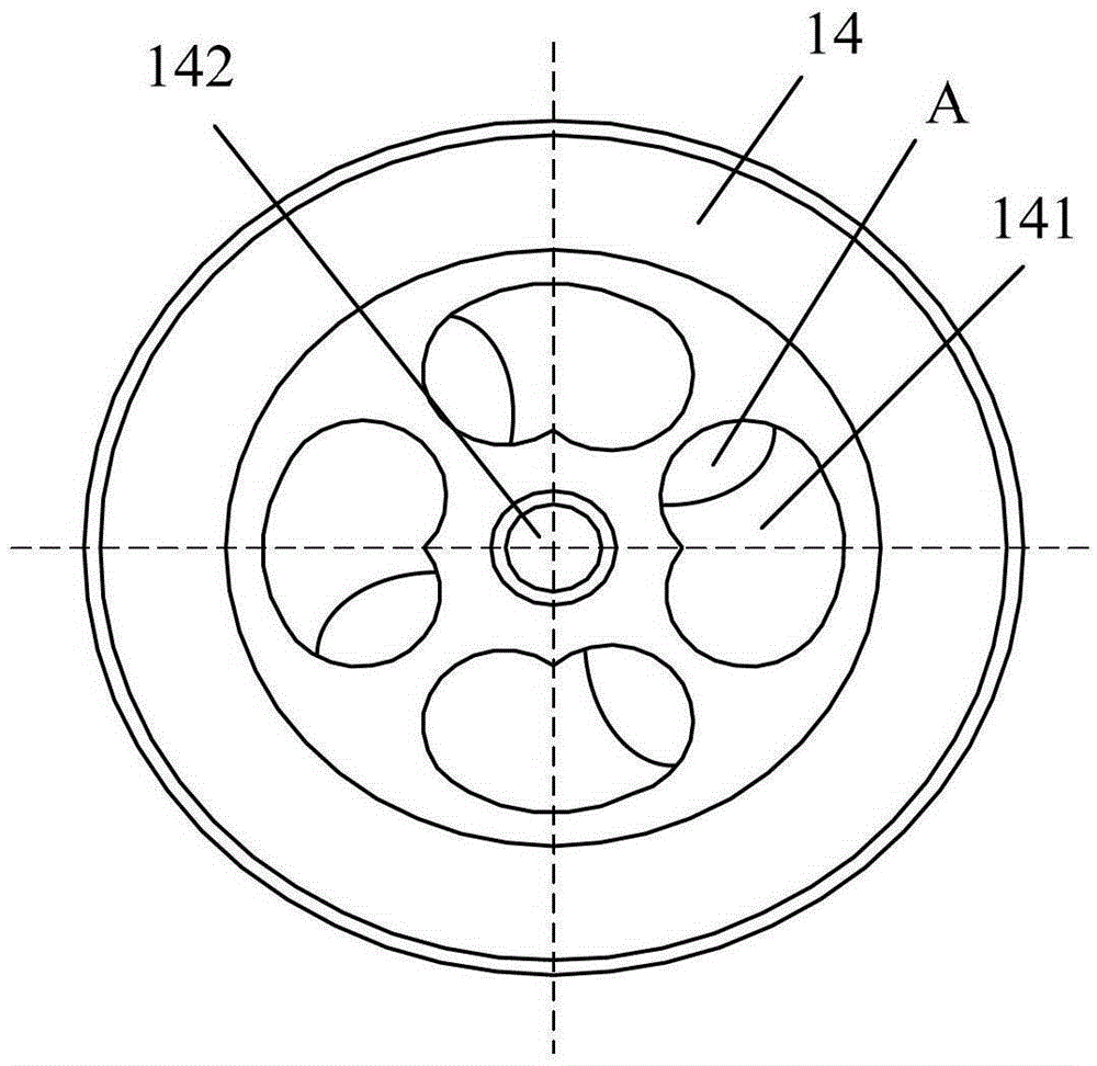
[0020] figure 1 It is a sectional view of the reverse water valve provided in the first embodiment of the present invention, figure 2 The front view of the reverse water valve seat provided in the first embodiment of the present invention Figure 1 , image 3 It is a top view of the reverse water valve seat provided in the first embodiment of the present invention, Figure 4 The front view of the reverse water valve seat provided in the first embodiment of the present invention Figure II , Figure 5 The front view of the reverse water valve seat provided in the first embodiment of the present invention Figure 3 , Image 6 The three-dimensional view of the reverse water valve seat provided in the first embodiment of the present invention Figure 1 , Figure 7 Stereoscopic view of the reverse water valve seat provided for the first embodiment of the present invention Figure II , Figure 8 The three-dimensional view of the reverse water valve seat provided in the fir...

Embodiment 2

[0030] Figure 9 It is a schematic cross-sectional structure diagram of the hydrodynamic energy-saving water pump provided in the second embodiment of the present invention. The fluid power energy-saving water pump can include a reverse water valve 1, a pump body 2, an air tank 3 and an impact valve 4, wherein the pump body 2 includes a water inlet, a reverse water opening and a water outlet, and the water outlet is fixedly provided with an impact valve 4. The tank 3 and the pump body 2 communicate with each other through the reverse water valve 1 at the reverse water port. like Figure 9 In the sectional view of the energy-saving water pump shown, the left side of the pump body 2 is the water inlet, the right side is the drain outlet, and the top is the reverse water outlet. The pump body 2 also includes a pump body back cover 21 . At the water outlet, the pump body back cover 21 is fixedly connected with the pump body 2 through bolts, and the impact valve 4 is fixed inside...


PUM


Abstract

A check valve and fluid dynamic energy conservation water pump. The check valve (1) comprises a check valve cover (11), a check valve rod (12), a sealing ring (13), a check valve seat (14), and a check valve spring (15). The water-passing holes (141) in the check valve (1) are at least two in number, and the axis of each of the water-passing hole (141) is a straight line in a different plane from the axis of a central hole (142) of the check valve seat, or the axis of the water-passing hole (141) is a spiral revolving around the axis of the central hole (142) such that water flow ejects from the check valve (1) in a spiral shape. The fluid dynamic energy conversation water pump comprises a pump body (2), an air bottle (3), the check valve (1), and an impact valve (4). The pump body (2) comprises a water inlet, a check valve port, and a water outlet. The water outlet is provided with the impact valve (4). The air bottle (3) is in communication with the pump body at the check valve port via the check valve (1), the check valve being the check valve (1) provided in the present application. The check valve and fluid dynamic energy conservation water pump provided in the present invention can solve the problem that exiting water pumps exert relatively small compression on the gas inside air bottles, thereby enhancing the lift distance and the volume of a water pump.

Description

technical field [0001] The invention relates to water pump technology, in particular to a reverse water valve and a fluid power energy-saving water pump. Background technique [0002] A water pump is a mechanical device that lifts a low-lying water stream. Common water pumps include two types, one is a mechanical water pump that uses diesel, natural gas or coal as a driving force, and the other is an electric water pump that uses electricity as an energy source. Among them, the mechanical water pump consumes a lot of energy, which makes the operation cost high, and in the face of the current situation that the global non-renewable energy is decreasing day by day, the above-mentioned mechanical water pump can no longer meet the needs of the market. The working voltage and power of electric water pumps are relatively high, and there are certain safety hazards in the working process, and also consume a large amount of energy indirectly. [0003] A reverse water valve is usual...

Claims


Application Information

Patent Timeline
Patent Type & Authority Patents(China)
IPC IPC(8): F16K15/02F16K17/04F04D29/00
CPCF04B53/10F04F1/06F16K15/063
Inventor 付兰荣李昂
Owner 付兰荣
Why Eureka
Try Eureka