Generator motor and electric vehicle using same
一种发电电动机、电枢绕线的技术,应用在电动汽车、电动汽车充电技术、电机等方向,达到高输出密度化、提高冷却效果的效果
- Summary
- Abstract
- Description
- Claims
- Application Information
AI Technical Summary
Problems solved by technology
Method used
Image
Examples
Embodiment 1
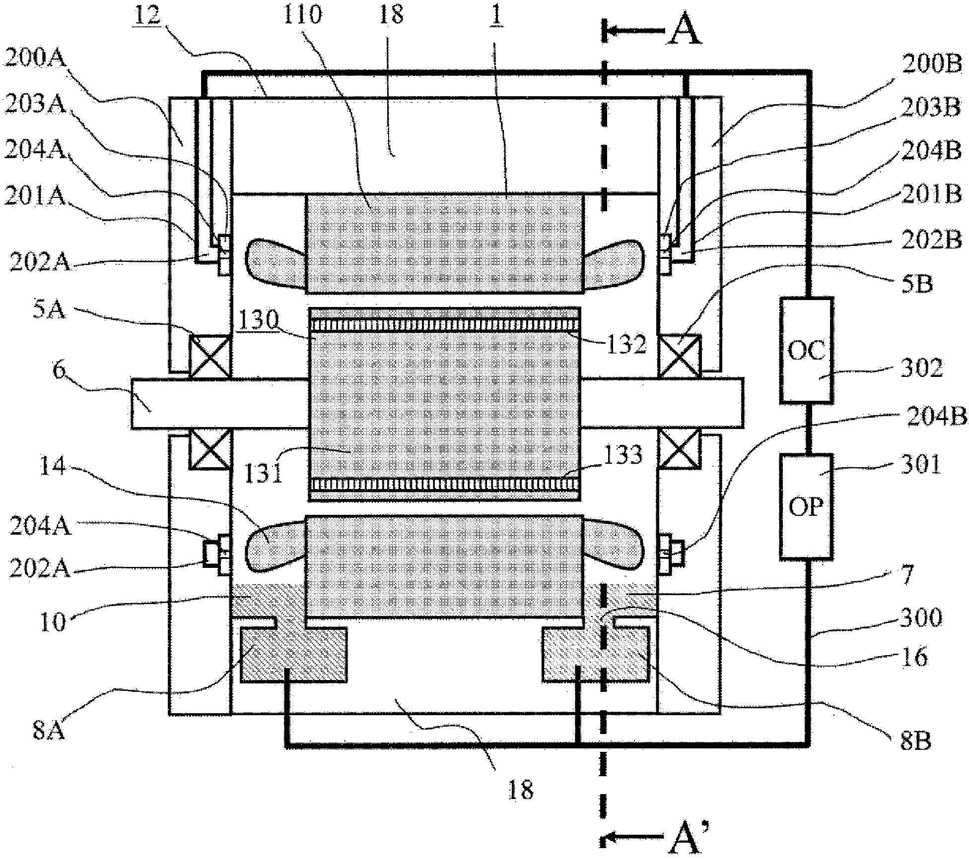
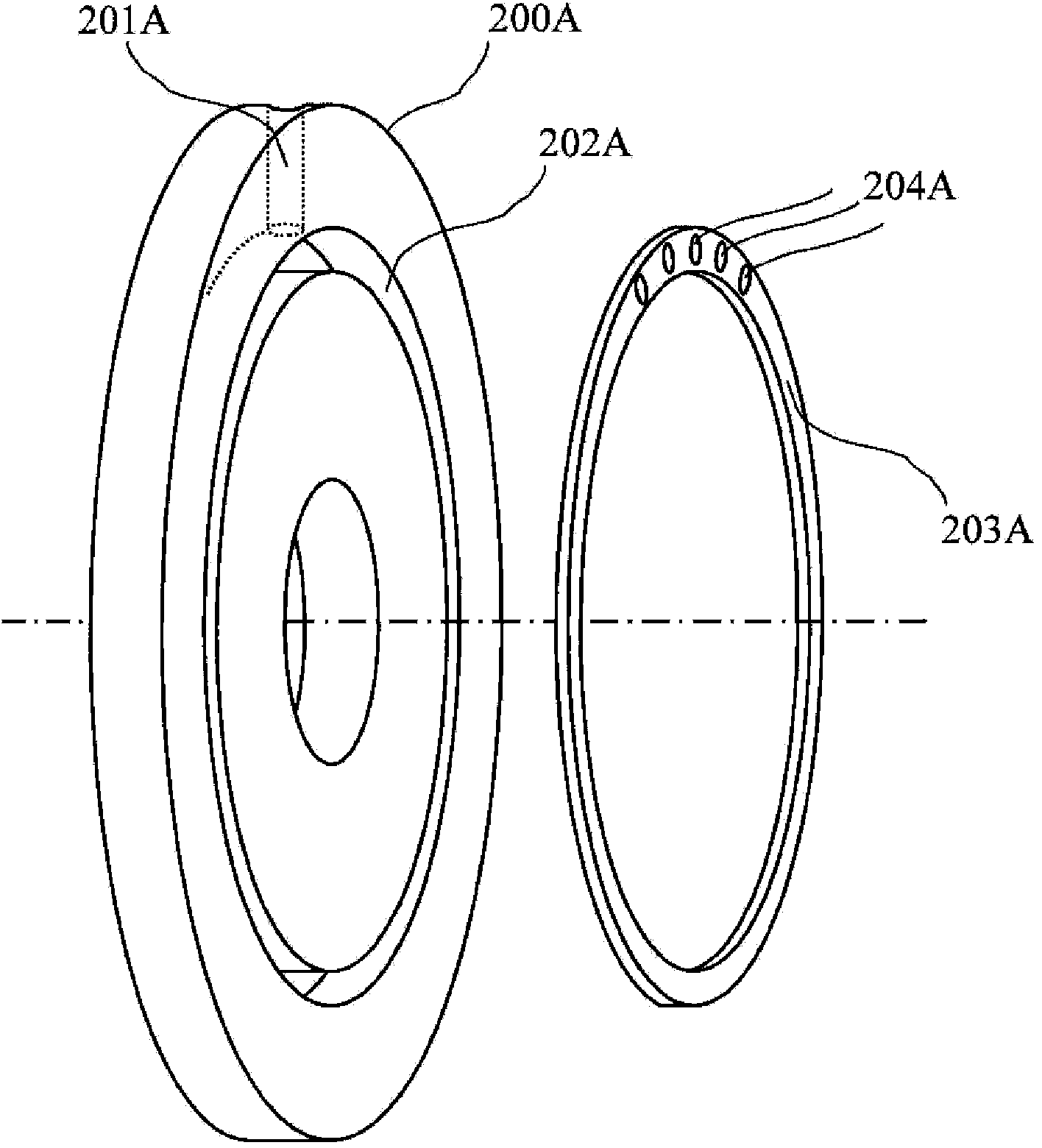
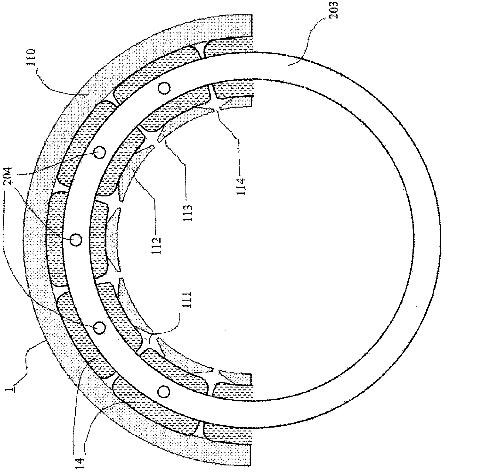
[0038] refer to Figure 1 to Figure 5 The generator motor according to the first embodiment of the present invention will be described in detail below. figure 1 It is an axial sectional view showing the overall structure of the generator motor according to the first embodiment of the present invention. figure 2 It is an exploded view showing the oil passage in the bracket of the generator motor of the first embodiment. image 3 It is a cross-sectional view showing the relationship between the armature windings and the positions of the oil injection holes in the generator motor of the first embodiment. Figure 4 is a cross-sectional view perpendicular to the axis of the housing of the generator motor and the auxiliary oil reservoir in the first embodiment, and is figure 1 The A-A' section plane view. Figure 5 It is a figure which shows the measurement result of the temperature distribution of the armature winding of the generator motor of 1st Example.
[0039] exist figu...
Embodiment 2
[0055] refer to Figure 6 A generator motor according to a second embodiment of the present invention will be described below. Figure 6 It is a cross-sectional view showing the relationship between the armature winding and the diameter of the oil injection hole in the generator motor of the second embodiment. exist Figure 6 in, for with image 3 The same constituent elements are attached with the same symbols to avoid repeated explanations.
[0056] The second embodiment and image 3 The first embodiment shown is different in that the oil injection holes 204 provided in the ring 203 are provided on the entire circumference so that the diameter of the oil injection holes 204 is larger in the vertical direction, smaller in the horizontal direction, and smaller in the vertical direction. In other words, the second embodiment is an example in which the diameter of the injection hole 204 provided on the bracket 200 is increased vertically above the bracket 200 and gradually b...
Embodiment 3
[0059] refer to Figure 7 A generator motor according to a third embodiment of the present invention will be described below. Figure 7 It is a cross-sectional view showing the relationship between the armature windings and the number and diameter of oil injection holes in the generator motor of the third embodiment. exist Figure 7 in, for with image 3 The same constituent elements are attached with the same symbols to avoid repeated explanations.
[0060] The third embodiment and image 3 The first embodiment shown is different in that the number of oil injection holes 204 provided in the ring 203 is more in the upper part in the vertical direction and decreases in the horizontal direction, and the diameter of the oil injection holes 204 is set at The upper part is larger in the vertical direction and smaller in the horizontal direction.
[0061] also, Figure 7 The illustrated example is an example of increasing the diameter of the spray hole when the number of spray...
PUM
 Abstract
Description
Claims
Application Information
 - R&D
- Intellectual Property
- Life Sciences
- Materials
- Tech Scout
- Unparalleled Data Quality
- Higher Quality Content
- 60% Fewer Hallucinations
Browse by: Latest US Patents, China's latest patents, Technical Efficacy Thesaurus, Application Domain, Technology Topic, Popular Technical Reports.
© 2025 PatSnap. All rights reserved.Legal|Privacy policy|Modern Slavery Act Transparency Statement|Sitemap|About US| Contact US: help@patsnap.com


