Method and device for preparing CO gas in real time

A technology of gas and cylinder, which is applied in the field of real-time preparation of CO gas, can solve the problems of hidden safety hazards in storage and use, and achieve the effect of solving the pressure of the tank and ensuring high temperature resistance

Active Publication Date: 2014-05-07
XIAN AEROSPACEMOTOR MACHINE FACTORY
View PDF5 Cites 1 Cited by
  • Summary
  • Abstract
  • Description
  • Claims
  • Application Information

AI Technical Summary

Problems solved by technology

[0004] In order to overcome the disadvantages in the prior art that there are relatively large safety hazards in storage and use, the present invention proposes a method and device for real-time preparation of CO gas

Method used


Image

  • Method and device for preparing CO gas in real time
  • Method and device for preparing CO gas in real time
  • Method and device for preparing CO gas in real time

Examples


Embodiment 1

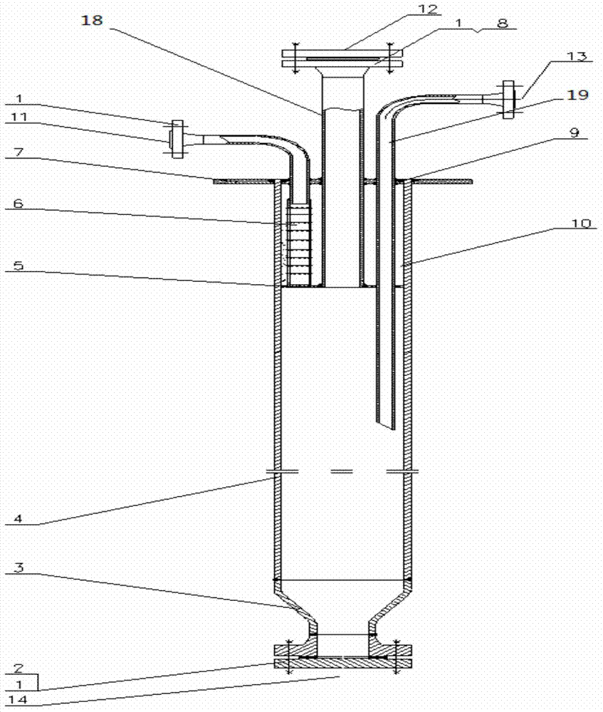
[0022] This embodiment is a device for preparing CO gas in real time, including a cylinder body 4 , a support plate 5 , a connecting pipe 6 , a contraction section 3 , a support plate 7 and an aluminum silicate fiber felt 10 .

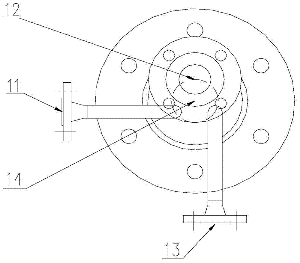
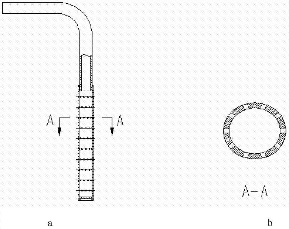
[0023] The lower end of the cylinder body 4 is welded with a shrinkage section 3 , and the upper end port of the cylinder body 4 is welded with a support plate 7 . One end of the charging pipe 18 passes through the eccentric through hole on the support plate 7 and is loaded into the cylinder body 4 . One end of the exhaust pipe 6 passes through the eccentric through hole on the support plate 7 and is loaded into the cylinder 4 . One end of the air inlet pipe 19 passes through the eccentric through hole on the support plate 7 and is packed into the cylindrical body 4 . The positions of the charging pipe 18, the exhaust pipe 6 and the air inlet pipe 19 on the support plate 7 are triangularly distributed. The support plate 5 is located at 1 / 5 of the cyl...

Embodiment 2

[0028] This embodiment is a method for real-time preparation of CO gas with a content of 2 to 10% by using the device for real-time preparation of CO gas, including the following steps:

[0029] Step 1, add activated carbon. Described activated carbon is made of charcoal or coconut shell, adopts charcoal to make in the present embodiment. Activated carbon is fed into the CO reaction tank from the feed port 12 of the CO reaction tank until the CO reaction tank is full. Seal the feed port of the CO reaction tank.

[0030] Step 2, the CO reaction tank is heated. The CO reaction tank is heated to 800-850°C by a heating furnace. The industrial nitrogen produced by membrane nitrogen production is passed into the CO reaction tank. The flow rate of the nitrogen is 5~10m 3 / h; the nitrogen concentration is 98.5-99.0%. After the nitrogen gas is introduced, the activated carbon in the CO reaction tank reacts with the trace oxygen in the nitrogen gas to form a mixed gas of CO and ni...


PUM


Abstract

The invention provides a method and a device for preparing CO (Carbonic Oxide) gas in real time. The device for preparing the CO gas having the content of 2-10% in real time comprises a cylinder, a support plate, an adapter, a contraction section, a support disc and an aluminum silicate fiber felt. The contraction section of which the taper is 30 degrees is formed at the lower end of the cylinder, while the support disc is welded on the port of the upper end of the cylinder. One end of a charging pipe penetrates through a via hole formed in the support disc and then is mounted in the cylinder. One end of an exhaust pipe penetrates through the via hole formed in the support disc and then is mounted in the cylinder. One end of a gas inlet pipe penetrates through the via hole formed in the support disc and then is mounted in the cylinder. While the CO gas is prepared, in order to prevent thermal treatment hydrogen embrittlement of ultrahigh-strength steel and solve the problem that hydrogen is contained in the existing thermal treatment protective atmosphere, the CO gas is taken instead of H2 and oxygen-free thermal treatment of products in a controllable atmosphere is realized.

Description

technical field [0001] The invention relates to a method and a device for real-time preparation of CO gas in a hydrogen-nitrogen-free protective atmosphere for heat treatment with a controllable atmosphere. Background technique [0002] In order to make high-strength steel and ultra-high-strength steel exert high strength and excellent plasticity and toughness requirements, these materials usually need to be heat-treated to exert the excellent performance of the material itself. The development direction of heat treatment is less oxidation-free heat treatment, vacuum heat treatment and nitrogen-based atmosphere protection heat treatment are the focus of research. At present, the nitrogen-based controlled atmosphere heat treatment reported in the literature all uses nitrogen plus reducing gas H 2 As a protective atmosphere to eliminate the residual oxygen in the atmosphere to achieve the purpose of non-oxidative heat treatment. However, ultra-high-strength steel is very sen...

Claims


Application Information

Patent Timeline
Patent Type & Authority Applications(China)
IPC IPC(8): C01B31/18C21D1/74C01B32/40
Inventor 张焱张曦宁李敏杜英军张立武王维朱晓冬周转红余大兵何楠邓军风尚勇孙晓峰龚远峦杨艳艳沈菊延朱赟
Owner XIAN AEROSPACEMOTOR MACHINE FACTORY
Why Eureka
Try Eureka