Castables for slag retaining walls and slag retaining walls

A technology of slag retaining wall and pouring material, which is applied in the direction of casting melt containers, manufacturing tools, metal processing equipment, etc., can solve the problems of not achieving the best thermal strength, affecting the use of tundish, and low strength of slag retaining wall, etc. Achieve the effect of low cost, good absorption and good thermal shock resistance

Active Publication Date: 2015-11-25
ANHUI SAFE ELECTRONICS
View PDF4 Cites 0 Cited by
  • Summary
  • Abstract
  • Description
  • Claims
  • Application Information

AI Technical Summary

Problems solved by technology

[0003] The technical problem to be solved by the present invention is that the slag retaining wall formed by mixing magnesia and corundum sand has low strength, cannot achieve the best thermal strength, and has a low service life, which affects the use of the tundish, thereby providing the slag retaining wall castable and slag retaining wall

Method used


Image

  • Castables for slag retaining walls and slag retaining walls
  • Castables for slag retaining walls and slag retaining walls

Examples


Embodiment 1

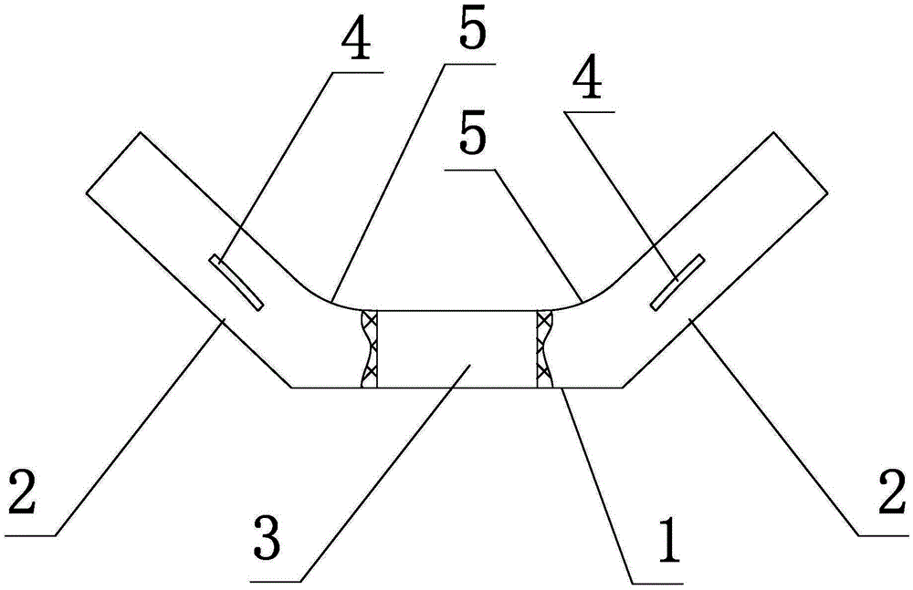
[0019] The castable for the slag retaining wall is composed of the following components in weight percentage: 12.7% of 8-20mm bauxite, 12.9% of 5-8mm bauxite, 14.5% of 3-5mm bauxite, 15.8% of 1-3mm bauxite, 0~ 12.8% of 1mm bauxite, 13.6% of bauxite with a particle size of 200 mesh, 3.3% of 0-1mm magnesia, 8.35% of magnesia with a particle size of 200 mesh, 4.35% of silicon micropowder, 1.5% of steel fiber, 0.1% of sodium hexametaphosphate, explosion-proof Fiber 0.1%.

Embodiment 2

[0021] The castable for the slag retaining wall is composed of the following components in weight percentage: 12% of 8-20mm bauxite, 12% of 5-8mm bauxite, 20% of 3-5mm bauxite, 15% of 1-3mm bauxite, 0-3mm bauxite 12% 1mm bauxite, 12.5% ​​bauxite with a particle size of 200 mesh, 3% magnesia with a particle size of 200 mesh, 8% magnesia with a particle size of 200 mesh, 4% silicon powder, 1.4% steel fiber, 0.06% sodium hexametaphosphate, explosion-proof Fiber 0.04%.

Embodiment 3

[0023] The castable for the slag retaining wall is composed of the following components in weight percentage: 11.2% of 8-20mm bauxite, 11.3% of 5-8mm bauxite, 25.5% of 3-5mm bauxite, 14.4% of 1-3mm bauxite, 0~ 10.9% 1mm bauxite, 11.7% bauxite with a particle size of 200 mesh, 2.7% magnesia with a particle size of 0-1mm, 7.65% magnesia with a particle size of 200 mesh, 3.65% silicon micropowder, and 1% steel fiber.

[0024] Al in the 8-20mm bauxite 2 o 3 content, Al in 5 ~ 8mm bauxite 2 o 3 content, Al in 3~5mm bauxite 2 o 3 content, Al in 1 ~ 3mm bauxite 2 o 3 content, Al in 0~1mm bauxite 2 o 3 content, Al in bauxite with a particle size of 200 mesh 2 o 3 The content of MgO in the 0-1mm magnesia and the MgO content in the magnesia with a particle size of 200 mesh are all equal to 88%. 95%, so that the magnesia has the characteristics of bending resistance, pressure resistance, high strength, etc., and improves the strength and bending resistance of the slag retainin...


PUM

PropertyMeasurementUnit
particle sizeaaaaaaaaaa

Abstract

The invention relates to a pouring material for a slag stopping wall. The pouring material consists of the following components: 8mm to 20mm alumina, 5mm to 8mm alumina, 3mm to 5mm alumina, 1mm to 3mm alumina, 0 to 1mm alumina, alumina with the granularity of 200 meshes, 0 to 1mm magnesium sand, magnesium sand with the granularity of 200 meshes, silicon micro powder, steel fiber, sodium hexametaphosphate and explosion-proof fibers. The slag stopping wall which is prepared by mixing the components comprises a plane wall body and slope wall bodies which are arranged on two sides of the plane wall body, wherein the bottom end of the plane wall body is provided with at least one flow steel hole, the top end of each slope wall body is provided with at least one suspension ring, and an arc chamfer angle is arranged on the junction of the plane wall body and the slope wall body. The slag stopping wall has the advantages that the slag stopping wall which is prepared by mixing the components is good in thermal shock resistance, optimal in hot strength under the working temperature, effective for absorbing Al2O3 in impurities, low in cost and good in service life.

Description

technical field [0001] The invention relates to a pouring material for a slag retaining wall and a slag retaining wall. Background technique [0002] In the process of iron and steel smelting, due to the uneven flow of molten steel in the tundish, some places are fast and some places are slow, especially there is an inactive stagnant zone of molten steel in the bottom area of ​​the tundish, which makes it difficult for inclusions to float up, and molten steel in the tundish The actual average residence time is shorter than the theoretical average residence time. In order to fully and effectively utilize the volume of the tundish and promote the floating of debris, a slag retaining wall is added to the tundish. Most of the existing castables for slag retaining walls use magnesia It is mixed with corundum sand, so that the strength of the slag retaining wall after the manufacture is low, the best thermal strength cannot be achieved, the service life is low, and the dead zone a...

Claims


Application Information

Patent Timeline
Patent Type & Authority Patents(China)
IPC IPC(8): C04B35/66B22D41/00
Inventor 李开胜
Owner ANHUI SAFE ELECTRONICS
Why Eureka
Try Eureka