Honeycomb structure body

a structure body and honeycomb technology, applied in the field of honeycomb structure bodies, can solve the problems of disadvantageously generating defects, affecting the heat shock resistance of the exhaust gas, and affecting the heat shock resistance of the exhaust gas, and achieve excellent heat shock resistance and heat shock resistance. excellent

Active Publication Date: 2013-11-28
NGK INSULATORS LTD
View PDF4 Cites 11 Cited by
  • Summary
  • Abstract
  • Description
  • Claims
  • Application Information

AI Technical Summary

Benefits of technology

[0019]A honeycomb structure body of the present invention includes a plurality of honeycomb segments, and joining material layers which join the plurality of honeycomb segments, and a ratio of the number of pores having a value of 1.2 or less which is obtained by dividing a maximum diameter of each of the pores by a minimum diameter of the each of the pores is 60% or more of the number of all the pores of each of the joining material layers. When the ratio of the number of the pores having the value of 1.2 or less which is obtained by dividing the maximum diameter by the minimum diameter is 60% or more of the number of all the pores as described above, it is possible to obtain the joining material layers in which a stress relaxing function is compatible with a joining strength. Moreover, the honeycomb structure body including these joining material layers has a heat shock resistance more excellent than that of a conventional honeycomb structure body, even when a material similar to a material constituting joining material layers of the conventional honeycomb structure body is used. That is, the honeycomb structure body of the present invention, including the joining material layers of the stress relaxing function and joining strength equivalent to those of the joining material layers of the conventional honeycomb structure body, has the excellent heat shock resistance.

Problems solved by technology

Moreover, when the exhaust gas passes through the partition wall, the particulate matter (the particulates) in the exhaust gas is trapped by the partition wall.
However, at the regeneration of this filter, a large heat stress (hereinafter referred to simply as “the stress” sometimes) takes place in the filter, and hence this heat stress disadvantageously generates defects such as cracks or breakdowns in the honeycomb structure body.

Method used


Image

  • Honeycomb structure body
  • Honeycomb structure body
  • Honeycomb structure body

Examples


example 1

Preparation of Honeycomb Segment

[0091]As ceramic raw materials, SiC powder and metal Si powder were mixed at a mass ratio of 80:20. To this mixture, methylcellulose and hydroxypropoxyl methylcellulose as forming auxiliaries, starch and a water-absorbing resin as pore formers, a surfactant and water were added, and kneaded, to prepare a kneaded material having a plasticity by a vacuum clay kneader.

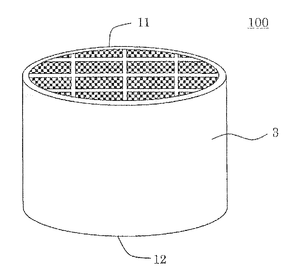
[0092]The obtained kneaded material was extruded by using an extruder, and dried by microwaves and hot air, to form a formed honeycomb body having porous partition walls with which a plurality of cells to become through channels of a fluid were formed, and an outer peripheral wall positioned at the outermost periphery. The obtained formed honeycomb body was subjected to high-frequency dielectric heating drying, and then dried at 120° C. for two hours by use of a hot air drier, to cut both end surfaces as much as a predetermined amount.

[0093]The obtained formed honeycomb body was dried at 12...


PUM

PropertyMeasurementUnit
porosityaaaaaaaaaa
pore diameteraaaaaaaaaa
bending strengthaaaaaaaaaa

Abstract

There is disclosed a honeycomb structure body having joining material layers of a stress relaxing function and joining strength equivalent to those of joining material layers of a conventional honeycomb structure body, and having an excellent heat shock resistance. A honeycomb structure body includes a plurality of honeycomb segments and joining material layers having a plurality of pores and joining the plurality of honeycomb segments in a state where the honeycomb segments are arranged adjacent to each other so that side surfaces of the honeycomb segments face each other. A ratio of the number of pores having a value of 1.2 or less which is obtained by dividing a maximum diameter of each of the pores by a minimum diameter of the each of the pores is 60% or more of the number of all the pores of each of the joining material layers.

Description

TECHNICAL FIELD[0001]The present invention relates to a honeycomb structure body. More particularly, the present invention relates to a honeycomb structure body having joining material layers of a stress relaxing function and joining strength equivalent to those of joining material layers of a conventional honeycomb structure body, and having an excellent heat shock resistance.BACKGROUND ART[0002]As a collecting filter for an exhaust gas, for example, a diesel particulate filter (DPF) to trap and remove a particulate matter (particulates) included in an exhaust gas from a diesel engine or the like, a honeycomb structure body has broadly been used.[0003]Such a honeycomb structure body has, for example, a structure in which a plurality of cells formed by porous partition walls made of silicon carbide (SiC) or the like to become through channels of a fluid are arranged in parallel with one another in a central axis direction. Moreover, end portions of the adjacent cells are plugged alt...

Claims


Application Information

Patent Timeline
Patent Type & Authority Applications(United States)
IPC IPC(8): C04B38/00
CPCC04B38/0009F01N3/0222F01N2330/06F01N2330/60C04B35/573C04B35/636C04B35/6365C04B37/005C04B38/0019C04B2111/00793C04B2235/3418C04B2235/428C04B2235/5228C04B2235/5296C04B2235/5436C04B2237/062C04B2237/064C04B2237/066C04B2237/068C04B2237/083C04B2237/365Y10T428/24149Y02T10/12B01D46/24492B01D46/24491B01D46/2448B01D46/2478B01D46/24495C04B35/00C04B38/0074C04B38/0051B01D46/2466B01D46/2425B01D46/2482
Inventor TAKAHASHI, NOBUAKIKODAMA, SUGURU
Owner NGK INSULATORS LTD
Why Eureka
Try Eureka